Catalog excerpts

BEVEL GEARBOXES
Open the catalog to page 1
“CHARACTER ROBOTS CAN CREATE ROBOTS WITH EMPATHY.” DAVID HANSON ROBOTICS AND ARTIFICIAL INTELLIGENCE DESIGNER AND RESEARCHER
Open the catalog to page 3
BEVEL GEARBOXES Sizes There are different bevel gearbox placement options on all the different sizes. The most common are 0 and 1. Although there are also others (see multi-shaft chapter) There are also different input shaft positions (A, B and AB). Input hollow shaft Solid input shaft In addition to the standard range of bevel gearboxes, NIASA can specifically develop the unit that best meets your application requirements. Contact NIASA.
Open the catalog to page 5
BEVEL GEARBOXES STANDARD PRODUCT DESCRIPTION Gearbox Compact design, with adjusted tolerances and modular casting iron and spherical graphite manufacturing. Necessary for working temperatures >50ºC. Optionally aeration and venting filters manufactured in plastic with integrated grease separator are mounted. They are mounted on the sides of the gearbox with tube elbows. Solid shafts / Hollow shafts …… …… …… …… …… …… …… Adjusted tolerances j6 and H7. Alignment hole S/DIN 332/2. Keyways S/DIN 6885/1. Keyway tolerance on hollow shafts JS9. Grooves for circlips S/DIN 472/1. Concentricity,...
Open the catalog to page 7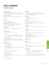
BEVEL GEARBOXES technical data Possibilities for use Universal use in all areas of machining and industrial plants. Adaptable modular system with a large number of variations. >98% for normal torque and single teeth fastening. For further details (according to assembly position, lubrication and sealing), please contact NIASA. Assembly orientation The bevel gearbox sides are defined with the letters from A to F. Control Possible from all shafts. Gearbox with motor / servomotor All bevel gearboxes can be supplied with the motor/ servomotor already assembled. For this option, send...
Open the catalog to page 8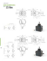
BEVEL GEARBOX SIZE 0 Shaft input position Shaft input position
Open the catalog to page 9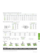
Nominal power /Nominal and maximum torque at the input (P1Nt=2,2) Maximum admissible forces on shafts (≤0.5 x T2N Ball bearings*) *Conical roller bearings if > 0.5 x T2N. Please contact NIASA Bevel gearbox weight (kg) VL0 AB1 2.9 Angular precision Assembly side Placing an order Model VL Shaft input position A Shaft input speed 1,000 *There is a possibility of supplying the bevel gearboxes with reinforced bearings, special lubrications or fastening flanges for motors and servomotors. For any of these options, please contact NIASA.
Open the catalog to page 10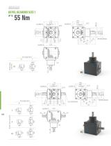
BEVEL GEARBOX SIZE 1 Shaft input position Shaft input position
Open the catalog to page 11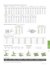
Nominal power /Nominal and maximum torque at the input (P1Nt=4,2) Maximum admissible forces on shafts (≤0.5 x T2N Ball bearings*) *Conical roller bearings if > 0.5 x T2N. Please contact NIASA Bevel gearbox weight (kg) VL1 AB1 6.7 Angular precision Assembly side Placing an order Model VL Shaft input position A Shaft input speed 1,000 *There is a possibility of supplying the bevel gearboxes with reinforced bearings, special lubrications or fastening flanges for motors and servomotors. For any of these options, please contact NIASA.
Open the catalog to page 12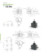
Shaft input position BEVEL GEARBOX SIZE 2 Shaft input position
Open the catalog to page 13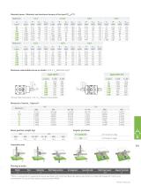
Nominal power /Nominal and maximum torque at the input (P1Nt=7,1) Maximum admissible forces on shafts (≤0.5 x T2N Ball bearings*) *Conical roller bearings if > 0.5 x T2N. Please contact NIASA Bevel gearbox weight (kg) VL2 AB1 15.3 Angular precision Assembly side Placing an order Model VL Shaft input position A Shaft input speed 1,000 *There is a possibility of supplying the bevel gearboxes with reinforced bearings, special lubrications or fastening flanges for motors and servomotors. For any of these options, please contact NIASA.
Open the catalog to page 14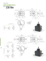
BEVEL GEARBOX SIZE 15 Shaft input position Shaft input position
Open the catalog to page 15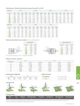
Nominal power /Nominal and maximum torque at the input (P1Nt=10,8) Maximum admissible forces on shafts (≤0.5 x T2N Ball bearings*) *Conical roller bearings if > 0.5 x T2N. Please contact NIASA Bevel gearbox weight (kg) VL15 AB1 22.8 Angular precision Assembly side Placing an order Model VL Shaft input position A Shaft input speed 1,000 *There is a possibility of supplying the bevel gearboxes with reinforced bearings, special lubrications or fastening flanges for motors and servomotors. For any of these options, please contact NIASA.
Open the catalog to page 16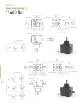
BEVEL GEARBOX SIZE 25 Shaft input position Shaft input position
Open the catalog to page 17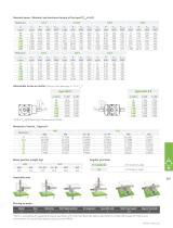
Nominal power /Nominal and maximum torque at the input (P1Nt=16,8) Admissible forces on shafts (Conical roller bearings if > 0.5 x T2N*) *≤0.5 x T2N Ball bearings. Please contact NIASA Bevel gearbox weight (kg) VL25 AB1 34.0 Angular precision Assembly side Placing an order Model VL Shaft input position A Shaft input speed 1,000 *There is a possibility of supplying the bevel gearboxes with reinforced bearings, special lubrications or fastening flanges for motors and servomotors. For any of these options, please contact NIASA.
Open the catalog to page 18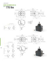
BEVEL GEARBOX SIZE 30 Shaft input position Shaft input position
Open the catalog to page 19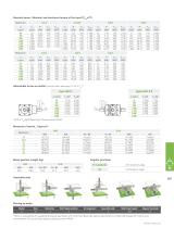
Nominal power /Nominal and maximum torque at the input (P1Nt=27) Admissible forces on shafts (Conical roller bearings if > 0.5 x T2N*) *≤0.5 x T2N Ball bearings. Please contact NIASA Bevel gearbox weight (kg) VL30 AB1 58.5 Angular precision Assembly side Placing an order Model VL Shaft input position A Shaft input speed 1,000 *There is a possibility of supplying the bevel gearboxes with reinforced bearings, special lubrications or fastening flanges for motors and servomotors. For any of these options, please contact NIASA.
Open the catalog to page 20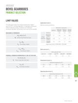
BEVEL GEARBOXES PRODUCT SELECTION LIMIT VALUES The admissible loads may produce temperatures higher than the 95°C in the bevel gearbox, if it operates continuously without adequate cooling. To prevent over-heating in continuous operation, the thermal limit must not be exceeded MECHANICAL THRESHOLD M Torque required at the input Machine working conditions Application factor s/DIN 3390 / ISO 6336 THERMAL THRESHOLD OPERATING AT 100% OF THE TIME P Power required at the input Operating time factor C4 Operating temperature (%)
Open the catalog to page 22All NIASA catalogs and technical brochures
-
Screw Jacks
50 Pages
-
Ball Screw Drives
36 Pages
-
Screw Supports
24 Pages
-
LINEAR TABLES
19 Pages
-
RODLESS MECHANICAL CYLINDERS
16 Pages

