


N83624 series User Manual multi channel programmable battery cell simulator

N83624 series User Manual multi channel programmable battery cell simulator
This manual provides detailed guidance on the N83624 series High Performance Multi-channel Battery Simulator by Hunan Next Generation Instrumental T&C Tech. Co., Ltd., covering installation, operation, and specifications. The company specializes in high-quality, technology-leading test and control instruments.
Safety Instructions
Users must follow safety instructions to ensure proper operation and maintenance. Key symbols include DC, AC, ground, and warnings for electric shock and high temperature. Safety precautions include confirming AC input voltage, reliable grounding, correct fuse installation, and avoiding hazardous conditions.
Inspection & Installation
Upon receiving the N83624, inspect for damage and verify accessories. Ensure the power cord is connected correctly, matching the instrument's rated voltage. Use the supplied power cord and connect to a grounded socket. If the device fails to start, check connections and replace the fuse if necessary.
Product Overview
The manual details the product's dimensions, optional accessory installation, and front and rear panel introductions. It covers button functions, channel interfaces, and communication ports like RS232, LAN, and CAN.
Operation
Instructions for interface navigation, parameter setting, and operation examples for source, charge, SOC edit, SOC test, SEQ edit, and SEQ test are provided. The system section includes communication settings and other parameters, while protection and fault simulation are also covered.
Maintenance and Self-Inspection
Regular maintenance and fault self-inspection procedures are outlined to ensure optimal performance.
Main Technical Data
The manual concludes with technical specifications of the N83624 series.
The N83624 is a programmable battery simulator designed for low-power, multi-channel, and high-accuracy applications. It supports both local and remote operations via LAN, RS232, and CAN interfaces. The device is capable of μA-level current measurement and offers up to 24 isolated channels, making it suitable for complex test environments.
Specifications
- Voltage range: 0~6V/0~15V
- Current range: 0~1A/0~3A/0~5A
- Voltage accuracy: up to 0.6mV
- Fast communication response: within 10ms for all channels
- High integration: standalone up to 24 channels
- Fast dynamic response: voltage rise time less than 20μs
- Interfaces: LAN, RS232, CAN
Dimensions
The regular dimension of the N83624 series is 132.5mm(H) x 482.0mm(W) x 559.0mm(D). An optional dimension with the NB108-2 accessory adds an additional depth of 166.9mm.
Installation
To install the optional NB108-2 accessory, ensure the power is off, attach the bracket to the rear panel, connect the power control cable and channel harness, and secure the accessory with screws.
Front Panel Features
The front panel includes a power switch, display screen, operation buttons, and a knob for parameter adjustments. It allows users to control the device and set parameters for various functions such as battery simulation and SEQ tests.
Rear Panel Features
The rear panel includes interfaces for channel output, CAN, RS232, LAN, and AC power. It supports high current outputs with a four-wire system to compensate for voltage drops.
Communication Interfaces
The N83624 supports communication via RS232, LAN, and CAN interfaces, allowing for flexible remote control options. The default IP address is 192.168.0.123, and the default baud rate is 115200.
Operation Modes
The device operates in various modes including Source, Charge, Battery, SOC Test, and SEQ Test. Each mode allows for specific parameter settings such as voltage, current limit, and resistance.
Example Operations
Examples are provided for setting parameters in Source and Charge modes, demonstrating how to select channels, set voltage and current limits, and enable outputs for testing.
The document explains that during the charging and discharging process, a larger battery capacity results in higher open circuit voltage and lower internal resistance. Conversely, a decrease in capacity leads to lower voltage and higher resistance.
SOC Edit
Users can edit up to 8 files with 200 steps each to form a test program. Parameters such as capacity, constant voltage, current limit, and internal resistance can be configured. Methods to enter SOC Edit include using the front panel or menu navigation.
Parameter Setting
Users can select channels, set file numbers, total steps, and specific step numbers. Parameters like capacity, constant voltage, simulated resistance, and output current limit are adjustable.
Operation Example
An example is provided for setting parameters for a lead-acid battery discharge model, detailing steps and corresponding values for capacity, voltage, current limit, and resistance.
SOC Test
After editing, users can execute SOC tests by selecting channels and setting initial voltage. The document provides steps for entering SOC Test mode and setting parameters.
SEQ Edit
Similar to SOC Edit, SEQ Edit allows editing of multiple steps with parameters like constant voltage, current limits, resistance, and dwell time. Links between steps and cycle times can be set.
SEQ Test
This section describes executing sequence tests based on edited SEQ files, with steps for setting parameters and running tests.
Graph and All View
Users can view voltage graphs for channels and an overview of voltage, current, and power values for all channels.
System Settings
The system configuration includes setting IP addresses, baud rates, language, and network connections. Options for device key sound and setting rates are also available.
CAN Set
Users can configure CAN ID addresses and baud rates, with options for extended CAN ID addresses and data upload intervals.
Protection
The document mentions a protection interface where users can set protection parameters.
The document outlines several protection mechanisms for the device, including Over Voltage Protection (OVP), Over Current Protection (OCP), and Over Power Protection (OPP). Each protection mechanism limits the respective output to a predefined value and shuts down the output immediately upon triggering, displaying a corresponding symbol on the screen.
Fault Simulation
The N83624 device can simulate various battery fault states such as short circuit, negative break, positive break, and reverse polarity. Fault simulation is only applicable in source mode and requires the channel to be turned off before activation.
Factory Reset
Users can restore factory settings by navigating through the menu and selecting the "Restore Factory" option.
About Us
The "About Us" section provides information on the factory serial number and software version of the N83624 device.
Maintenance and Self-inspection
Regular maintenance involves cleaning the device with a dry or slightly wet cloth while ensuring the power is disconnected. Fault self-inspection steps are provided to troubleshoot issues, and it is recommended to calibrate the device annually.
Main Technical Data
The document provides detailed technical specifications for various models of the N83624 series, including current, voltage, power, and channel specifications. It also includes information on dynamic characteristics, load regulation, remote compensation voltage, isolation, earth leakage current, communication response time, interface options, and environmental conditions.
Usage Note
When using multiple N83624 devices in series, ensure all channels are turned off before disconnecting the mains power to prevent damage.
Catalog excerpts

ELECTRONIC SOLUTION PROVIDER FOR INTELLIGENT MANUFACTURING User Manual N83624 Series High Performance Multi-channel Battery Simulator Hunan Next Generation Instrumental T&C Tech. Co., Ltd.
Open the catalog to page 1
ELECTRONIC SOLUTION PROVIDER FOR INTELLIGENT MANUFACTURING Copyright Statement Hunan Next Generation Instrumental T&C Tech. Co., Ltd. (NGI for short) Without the prior permission and written consent of NGI, no content in this manual may be reproduced in any form (including electronic storage and retrieval or translation into a foreign language). NGI shall not be liable for errors or for incidental or consequential damages in connection with the provision, use or application of this manual and any information contained herein. The information provided in this manual is subject to change without...
Open the catalog to page 2
ELECTRONIC SOLUTION PROVIDER FOR INTELLIGENT MANUFACTURING
Open the catalog to page 3
ELECTRONIC SOLUTION PROVIDER FOR INTELLIGENT MANUFACTURING 1 Preface Dear Customers First of all, we greatly appreciate your choice of N83624 series High Performance Multi-channel Battery Simulator (N83624 for short). We are also honored to introduce our company, Hunan Next Generation Instrumental T&C Tech. Co., Ltd.( NGI for short). About Company NGI is a professional manufacturer of intelligent equipment and test & control instruments, committed to developing, manufacturing battery simulators, power supplies, electronic loads, and many more instruments. The products can be widely used in the...
Open the catalog to page 5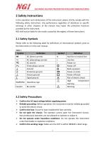
ELECTRONIC SOLUTION PROVIDER FOR INTELLIGENT MANUFACTURING 2 Safety Instructions In the operation and maintenance of the instrument, please strictly comply with the following safety instructions. Any performance regardless of attentions or specific warnings in other chapters of the manual may impair the protective functions provided by the instrument. NGI shall not be liable for the results caused by the neglect of those instructions. Please refer to the following table for definitions of international symbols used on the instrument or in the user manual. Table 1 2.2 Safety Precautions > Confirm...
Open the catalog to page 6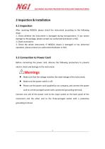
ELECTRONIC SOLUTION PROVIDER FOR INTELLIGENT MANUFACTURING 3 Inspection & Installation 3.1 Inspection After receiving N83624, please check the instrument according to the following steps: 1. Check whether the instrument is damaged during transportation. If any severe damage to the package, please contact our authorized distributor or NGI. 2. Check accessories. 3. Check the whole instrument. If N83624 chassis is damaged or has abnormal operation, please contact our authorized distributor or NGI. 3.2 Connection to Power Cord Before connecting the power cord, observe the following precautions to...
Open the catalog to page 7
ELECTRONIC SOLUTION PROVIDER FOR INTELLIGENT MANUFACTURING 1. Before connecting the power cord, please make sure that the power supply voltage matches the rated power supply voltage of this instrument. 2. To prevent electric shock and fire, use the power cord supplied by us. 3. To prevent electric shock, be sure to take protective grounding. Connect the power cord to a three-pronged socket with a protective earth terminal. When the device cannot start normally, please try the following solutions: 1. Check whether the power cord is connected properly, whether the device has been powered normally,...
Open the catalog to page 8
ELECTRONIC SOLUTION PROVIDER FOR INTELLIGENT MANUFACTURING 3.4 Wiring 3.4.1 Regular Wiring Figure 1 Regular wiring Figure 2 Optional wiring
Open the catalog to page 9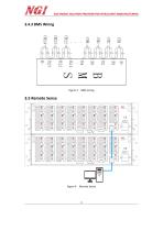
ELECTRONIC SOLUTION PROVIDER FOR INTELLIGENT MANUFACTURING Remote Sense
Open the catalog to page 10
ELECTRONIC SOLUTION PROVIDER FOR INTELLIGENT MANUFACTURING The N83624 can be connected to a computer via a network cable. Before powering on the computer, make sure that the wires are correctly connected and that the communication settings are correct.The N83624 series battery simulator can also be controlled by multiple units at the same time. For LAN communication, users need to connect the LAN to the computer through a network cable and a switch. Before powering on the computer, check if the connection is correct and make sure that the IP addresses of all N83624s are not duplicated. N83624...
Open the catalog to page 11
ELECTRONIC SOLUTION PROVIDER FOR INTELLIGENT MANUFACTURING 4 Product 4.1 Introduction N83624 is a programmable battery simulator with low-power, multi-channel and high-accuracy. Its voltage accuracy is up to 0.6mV, supporting pA-level current measurement, standalone up to 24 channels. The channels are isolated from each other, which is convenient for series connection. N83624 supports both local operation and remote operation via LAN/RS232/CAN interface. N83624 application software is easy to use, which can meet demands of battery simulators in multi-channel, multiparameter, and complex test...
Open the catalog to page 12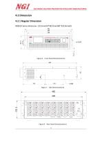
ELECTRONIC SOLUTION PROVIDER FOR INTELLIGENT MANUFACTURING 4.2 Dimension 4.2.1 Regular Dimension N83624 Series dimension: 132.5mm(H)*482.0mm(W)*559.0mm(D) Figure 6 Front Panel Dimension(mm) Figure 7 Side Dimension(mm) Rear Panel Dimension(mm) 9
Open the catalog to page 13
ELECTRONIC SOLUTION PROVIDER FOR INTELLIGENT MANUFACTURING 4.2.2 Optional Dimension N83624+NB108-2 Series Dimension: 132.5mm(H)*482.0mm(W)559.0mm(D)+166.9mm(D) Figure 9 Front Panel Dimension(mm) Rear Panel Dimension(mm) Side Dimension(mm)
Open the catalog to page 14
ELECTRONIC SOLUTION PROVIDER FOR INTELLIGENT MANUFACTURING Front Panel Dimension(mm) Rear Panel Dimension(mm) Side Dimension(mm)
Open the catalog to page 15
ELECTRONIC SOLUTION PROVIDER FOR INTELLIGENT MANUFACTURING 4.3 Optional Accessory Installation(NB108-2) The installation method of optional accessory can be carried out according to the following steps. 1. Turn off the AC input power and remove the power cord. 2. Take out the screws, and use a screwdriver to fix the bracket to the holes on the rear panel of N83624. Figure 15 Bracket Installation 3. Connect NB108-2 power control cable to N83624 power control terminal. 4. Connect NB108-2 channel harness to the channel interface of N83624, taking CH1 as an example. Figure 16 Wiring Harness Connection...
Open the catalog to page 16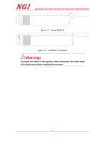
ELECTRONIC SOLUTION PROVIDER FOR INTELLIGENT MANUFACTURING Installation Completed To ensure the safety of the operator, please disconnect the input power of the instrument before installing the accessory.
Open the catalog to page 17All NGI Tech catalogs and technical brochures










- DC power supply
- AC/DC power supply
- Measuring device
- IO module
- CE power supply
- Single-output power supply
- Analog I/O
- Power supply for industrial applications
- Switched-mode power supply
- Compact power supply
- Tabletop power supply
- Industrial tester
- Fieldbus I/O module
- Voltage testing system
- Analog IO module
- Variable-output power supply
- Power supply with overload protection
- Laboratory power supply
- Single-phase power supply