- Company
- Products
- Catalogs
- News & Trends
- Exhibitions
NI10_DS
1 /23Pages

NI10_DS
1 /23Pages
Catalog excerpts

VIBRATING WIRE READER NI10 NI10 VIBRATING WIRE READER NI10 DIN BAR RS-485 MODBUS RTU VIBRATING WIRE READER USER MANUAL Rev. 02 del 20/10/2017 Redatto da R&D Approvato da MKT
Open the catalog to page 1
SPECIFIC WARNINGS To guarantee the IP protection during the installation, expect to seal the instrument cables (with silicone or foam) after having tightened the cable-gland. Through the installation expect suitable protections to avoid product overheating (eg. a shelter to avoid direct sunlight); similarly for low temperatures. Do not open in case of bad weather conditions (rain, snow, etc). Expect the recurring substitution of the hygroscopic salts. Do not install in small locations and/or without ventilation, with high humidity, in potentially dangerous areas or where is prescribed the use...
Open the catalog to page 2
NI10 - ONE CHANNEL VIBRATING WIRE 1 INTERFACE Features Use Cases 2 ELECTRICAL CONNECTION Overview Daisy Chain 3 USER INTERFACE LEDS Jumper Dip Switch COMMUNICATION Communication Parameters 4 Protocol Address Acronyms BOARD MANAGEMENT Procedure for the reading of a vibrating wire 5 sensor in Single-Shot (SSHOT) mode Flow chart of VW sensor acquisition in Single Shot (SSHOT) mode Procedure for the reading of a vibrating wire sensor in Continuous Mode (CMOD) Procedure for thermistor calibration APPENDIX A. Connection to Next Industries' NI-series data-6 logger (NI100, NI200, NI400, NI2400) APPENDIX...
Open the catalog to page 3
NI10 - ONE CHANNEL VIBRATING WIRE INTERFACE NI10 is an interface between a vibrating wire sensor and a data acquisition system. This device measures the resonance frequency and the temperature of the vibrating wire sensor. Most vibrating wire sensors on the market can be connected. Features The NI10 uses frequency sweep search and FFT processing technology to obtain the wire vibration frequency, together with a voltage excitation capability of 24V pk-pk max. This allows precise and repeatable measurements also in noisy environments and with long cables; a quality index is also calculated and...
Open the catalog to page 4
VIBRATING WIRE READER NI10 VIBRATING WIRE READER NI10 Sensor (Vibrating Wire and NTC) GND (shield) T- T+: Thermistor (NTC) clamps VW- VW+: Vibrating Wire clamps Daisy Chain Thanks to RS-485 and Modbus RTU protocol it's possible to connect up to 30 NI10 at 115200bps or 32 NI10 at 9600bps in daisy chain. Line termination Jumper (on last unit) could be needed for long cables. USER INTERFACE LEDs Green LED Green Led flashes every 4 seconds for a period of 500ms (reporting board turned on). For each Modbus packet received, the led is quickly blinking LED. Red LED Red Led means error or performed calibration...
Open the catalog to page 5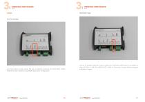
VIBRATING WIRE READER NI10 Jumper VIBRATING WIRE READER NI10 Line Termination Jumper allows the user to select the internal line termination resistor (120 Ohm) when needed in long RS485 daisy chain configuration. This set of jumpers allows the user to select the Thermistor (NTC) used. It's possible to select 3K Ohm or 10K Ohm (@25°C) NTC. Refer to Thermistor Jumper (0x66) paragraph in Modbus Chapter. .::iiiii.nc=x-r www.nextind.eu 111i 111111 ■ liini .;:;iii!ln<=XT www.nextind.eu *■ *■ ^ imlii' 11 ii■ <
Open the catalog to page 6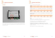
VIBRATING WIRE READER NI10 VIBRATING WIRE READER NI10 NI10 is equipped with a 6-way dip switch to set the device address (for Modbus RTU protocol). Switch 1 controls the Less Significative Bit of the address, while Switch 6 controls Most Significative Bit. To set a number here refer to this table: Switch 1 2 3 4 5 6 Example A. Number 5 is 4+1 so all switches are OFF except for 1 and 3 which are ON. Switch 1 2 3 4 5 6 Example B. Number 23 is 1+2+4+16 so all all switches are ON except for 4 and 6 which are OFF. Note: Address 0 (Zero) is not available in Modbus RTU. Address 63 is not available because...
Open the catalog to page 7
VIBRATING WIRE READER NI10 VIBRATING WIRE READER The communication at physical level with the VW boards is based on a RS485 bus. Communication Parameters Communication parameters are as it follows: Warning This section list Modbus address for the firmware versione 3.01. For different firmware version, refer to the Modbus Registers list pdf matching our firmware version VALUE Procedure for the reading of a vibrating wire sensor in Single-Shot (SSHOT) mode Speed 115200 bps Stop bit number Numero 1 Protocol Communication protocol is MODBUS RTU. The VW Vibrating Wire boards are SLAVE and meet all...
Open the catalog to page 8
VIBRATING WIRE READER NI10 VIBRATING WIRE READER NI10 Flow chart of VW sensor acquisition in Single Shot (SSHOT) mode Procedure for the reading of a vibrating wire sensor in Continuous Mode (CMOD) ^ower on Configure reading 'Acquisition result' 1) Turn on the board 2) Wait 2 seconds for the board to be initialized 3) Configure the parameters for the sensor reading (if the default values are not suitable for the sensor) - Write in the special registers; excitation, delay, start frequency and stop frequency (0x60, 0x61,0x62, 0x63 registers) - Set number of readings of cycles (0x64 register) equal...
Open the catalog to page 9
VIBRATING WIRE READER NI10 JL VIBRATING WIRE READER NI10 Procedure for thermistor calibration APPENDIX A. Turn the board on Connection to Next Industries' NI-series datalogger (NI100, NI200, NI400, NI2400) "LOW" point calibration Apply a 0.5V voltage between pin 1 (GND) and 2 (NTC) of the P2 connector Shotcut to GND SWCLK signal of JTAG (use the special keyboard) for at least 2 seconds. Red led flashes 4 times slowly: calibration is ok Read led does not flash: calibration is failed. Check applied voltage with a tester "HIGH" point calibration Apply a 2.5V between pin 1 (GND) and 2 (NTC) of the...
Open the catalog to page 10
VIBRATING WIRE READER NI10 Select SmartModbus And now you can populate fields to read NI10 (this is an example for Single Shot reading). .::iiiii.nc=x-r www.nextind.eu 111i 111 III' liiin
Open the catalog to page 11
VIBRATING WIRE READER VIBRATING WIRE READER NI10 NTC sensors (Measure B) needs a linear conversion with this parameters: Smart Mux with NI100 and NI10 Overview This manual is dedicated to Next Industries’ Smart Mux. This device offers a smart system to read Vibrating Wire sensors. Sections of this manual are structured to let the user learn advantages of the system, use the device in little to no time, then master and tweak it to his needs. • System Architecture illustrates how the system is developed, how is expandable • Quick start is a no-time consuming guide to learn how to start the first...
Open the catalog to page 12All Next Industries s.r.l catalogs and technical brochures
 NI74_DS
3 Pages
 IIot and Artificial Intelligence
20 Pages
 NI400_DS
8 Pages
 NI2400/NI816/NI4866 DATALOGGER
28 Pages
 NI100_DS
4 Pages
 TACTIGON ONE_DS
1 Page
 NI20X_DS
3 Pages
 NI71N_DS
3 Pages
 NIG80X_DS
4 Pages
 NI2400_DS
12 Pages


- Measuring device
- Data logger
- Digital I/O
- IO module
- Temperature datalogger
- Analog I/O
- Digital IO module
- USB datalogger
- Data-logger with screen
- Humidity and temperature probe
- Wireless datalogger
- Analog IO module
- Battery-powered datalogger
- Remote I/O
- Monitoring datalogger
- Compact I/O
- Programmable datalogger
- Waterproof humidity and temperature sensor
- Digital humidity and temperature sensor
- Remote IO module