- Catalogs
- Nexen Group, Inc.
- ECLIPSE PRODUCTS
- Company
- Products
- Catalogs
- News & Trends
- Exhibitions
ECLIPSE PRODUCTS
1 /14Pages

ECLIPSE PRODUCTS
1 /14Pages
Catalog excerpts

ECLIPSE PRODUCTS User Manual Eclipse Servo Brake Sizes 7, 9 and 11
Open the catalog to page 1
In accordance with Nexen's established policy of constant product improvement, the specifications contained in this manual are subject to change without notice. Technical data listed in this manual are based on the latest information available at the time of printing and are also subject to change without notice. This document is the original, non-translated, version. Conformity Declaration: In accordance with Appendix II B of CE Machinery Directive (2006/42/EC): A Declaration of Incorporation of Partly Completed Machinery evaluation for the applicable EU directives was carried out for this product...
Open the catalog to page 2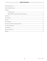
Table of Contents General Specifications ---------------------------------------------------------------------------------------------------------------------- 4 General Safety Precautions --------------------------------------------------------------------------------------------------------------- 4 Installation: Onto Motor Shaft -------------------------------------------------------------------------------------------------------------------- 5 Mounted Between a Motor Shaft and a Gear Reducer --------------------------------------------------------------- 6 Lubrication------------------------------------------------------------------------------------------------------------------------------------------7...
Open the catalog to page 3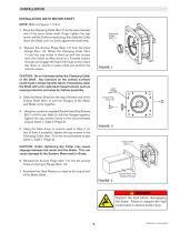
INSTALLATION INSTALLATION ONTO MOTOR SHAFT NOTE: Refer to Figures 1, 2 & 3. 1. lace the Clamping Collar (Item 7) on the input (female) P end of the servo brake shaft. Finger tighten the cap screw until the Collar is nearly snug, then slide the Collar down the Shaft until it is firmly against the shaft step. Clamping Collar (Item 7) 2. Remove the Access Plugs (Item 14) from the Input Flange (Item 10). Rotate the Clamping Collar (Item 7) until the cap screw is lined up with the access hole; then insert an Allen driver or a T-handle wrench through and engage the head of the cap screw. Leave this...
Open the catalog to page 5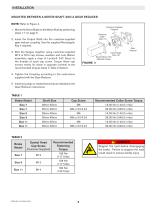
NOTE: Refer to Figure 4. 1. Mount the Servo Brake to the Motor Shaft by performing steps 1-7 on page 5. 2. I nsert the Output Shaft into the customer-supplied gear reducer coupling. Use the supplied Rectangular Key if required. 3. Bolt the flanges together using customer-supplied M12 or M14 cap screws, washers and nuts. Before assembly, apply a drop of Loctite® 242 (blue) to the threads of each cap screw. Torque these cap screws evenly (ie, those in opposite corners) to the recommended torques listed in Table 2 (below). 4. Tighten the Coupling according to the instructions supplied with the Gear...
Open the catalog to page 6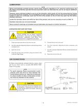
NOTE Nexen pneumatically actuated devices require clean, pressure regulated air for maximum performance and life. Nexen pneumatically operated devices pneumatic seals are lubricated life, and do not require additional lubrication. However, some customers prefer to use an air line lubricator, which injects oil into the pressurized air, forcing an oil mist into the air chamber. This is acceptable, but care must be taken to ensure once an air mist lubrication system is used, it is continually used over the life of the product as the oil mist may wash free the factory installed lubrication. Locate...
Open the catalog to page 7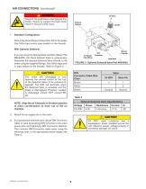
^_ A Support the load before disengaging the brake. Failure to support the load could result in serious bodily injury. 1. Standard Configuration: Attach the Quick Exhaust Valve (Item 23) to the brake. Use Teflon tape and/or pipe sealant on the threads. With Optional Solenoid: If you are using the optional Solenoid Valve (Nexen Part #964650), the Quick Exhaust Valve is unnecessary. Assemble the optional Solenoid Valve directly to the brake using the supplied fittings. Use Teflon tape and/ or pipe sealant on the threads. Refer to Figure 5.
Open the catalog to page 8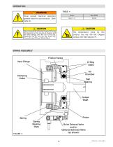
BRAKE ASSEMBLY Friction Facing
Open the catalog to page 9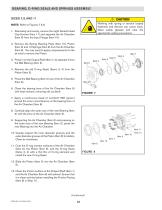
NOTE: Refer to Figures 7 & 8. 1. Alternately and evenly, remove the eight Socket Head Cap Screws (Item 11) and separate the Air Chamber (Item 6) from the Input Flange (Item 10). 2. Remove the Spring Backing Plate (Item 15), Piston (Item 5) and 10 Springs (Item 9) from the Air Chamber (Item 6). You may need to apply compressed air to the air inlet to remove the Piston. 3. Press in on the Output Shaft (Item 1) to separate it from the Ball Bearing (Item 2). 4. Remove the old O-ring Seals (Items 3, 4) from the Piston (Item 5). 5. Press the Ball Bearing (Item 2) out of the Air Chamber (Item 6). 6....
Open the catalog to page 10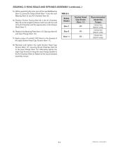
14. While supporting the inner race of the new Ball Bearing (Item 2), press the Output Shaft (Item 1) into the new Bearing (Item 2) and Air Chamber (Item 6). 15. Position Friction Facing (Item 8) in the Air Chamber (Item 6) so the angled surfaces match up with the wall of the Air Chamber and the tapered disc of the Output Shaft (Item 1). 16. Replace the Backing Plate (Item 15), Springs (Item 9) and Input Flange (Item 10). 17. Apply a drop of Loctite® 242 (blue) to the threads of the eight Socket Head Cap Screws (Item 11). 18. Reinstall and tighten the eight Socket Head Cap Screws (Item 11), securing...
Open the catalog to page 11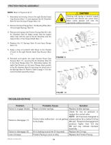
NOTE: Refer to Figures 9 & 10.
Open the catalog to page 12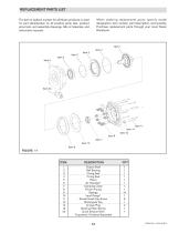
The item or balloon number for all Nexen products is used for part identification on all product parts lists, product price lists, unit assembly drawings, bills of materials, and instruction manuals. When ordering replacement parts, specify model designation, item number, part description, and quantity. Purchase replacement parts through your local Nexen Distributor.
Open the catalog to page 13
WARRANTY Warranties Nexen warrants that the Products will (a) be free from any defects in material or workmanship for a period of 12 months from the date of shipment, and (b) will meet and perform in accordance with the specifications in any engineering drawing specifically for the Product that is in Nexen’s current product catalogue, or that is accessible at the Nexen website, or that is attached to this Quotation and that specifically refers to this Quotation by its number, subject in all cases to any limitations and exclusions set out in the drawing. NEXEN MAKES NO OTHER WARRANTY, EXPRESS...
Open the catalog to page 14All Nexen Group, Inc. catalogs and technical brochures
 PRECISION MOTION CONTROL
56 Pages
 LINEAR MOTION CONTROL
4 Pages
 PRINCIPALS OF OPERATION
1 Page
 Precision in motion.
2 Pages
 Compact Ring Drive
14 Pages
 Precision Ring Drive
10 Pages
 ECLIPSE PRODUCTS User Manual
14 Pages
 Linear Couplings
2 Pages
 Eclipse Servo Motor Brake
2 Pages
 Zero Backlash Gear Catalog
30 Pages
 Torque Limiter Catalog
16 Pages
 Servo Brake Catalog
16 Pages
 Rod Lock Catalog
12 Pages
 Rail Brake Catalog
8 Pages
 Indexer Brake Catalog
2 Pages
 Clutch & Brake Catalog
388 Pages


- ERLO load cell
- ERLO coaxial gear reducer
- ERLO tension/compression load cell
- ERLO precision gear reducer
- ERLO strain gauge load cell
- ERLO compact gear reducer
- Solid-shaft gearhead
- Pressure separator filter
- ERLO signal amplifier
- ERLO gear reducer for industrial applications
- Friction brake
- Clamp gearbox
- Basket filter
- Disc brake
- Spring brake
- Friction brake caliper
- Electromagnetic brake
- High load capacity gear reducer
- Automatic filter