- Catalogs
- Nexen Group, Inc.
- Compact Ring Drive
- Company
- Products
- Catalogs
- News & Trends
- Exhibitions
Compact Ring Drive
1 /14Pages

Compact Ring Drive
1 /14Pages
Catalog excerpts

Precision Motion Control User Manual Compact Ring Drive Product Family: PL - Planetary Gearbox HG - Harmonic Gearhead DD - Direct Drive MRS - Motor Ready Sealed MRG - Motor Ready Guarded MRO - Motor Ready Open
Open the catalog to page 1
In accordance with Nexen's established policy of constant product improvement, the specifications contained in this manual are subject to change without notice. Technical data listed in this manual are based on the latest information available at the time of printing and are also subject to change without notice. This document is the original, non-translated, version. Conformity Declaration: In accordance with Appendix II B of CE Machinery Directive (2006/42/EC): A Declaration of Incorporation of Partly Completed Machinery evaluation for the applicable EU directives was carried out for this product...
Open the catalog to page 2
General Safety Precautions ---------------------------------------------------------------------------------------------------- 4 System Design Overview ------------------------------------------------------------------------------------------------------- 5 Mounting Surface Details ------------------------------------------------------------------------------------------------------- 6 Installation Instructions ---------------------------------------------------------------------------------------------------------- 7 Installation Instructions: Optional Brake-----------------------------------------------------------------------------------...
Open the catalog to page 3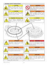
WARNING Deadly voltages can occur. Risk of electric shock. Check that all live connection points are safe against accidental contact. WARNING Ensure proper guarding of the product is used. Nexen recommends the machine builder design guarding in compliance with OSHA 29 CFR 1910 “Occupational Safety and Health Hazards”. DANGER This product has moving parts that can crush or cut appendages. Provide adequate spacing or guarding from any operating product. WARNING Always make sure that the motors are de-energized during assembly and wiring. Risk of electric shock. WARNING Never undo the electrical...
Open the catalog to page 4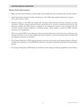
SYSTEM DESIGN OVERVIEW General System Requirements • Make sure the machine design is rigid enough to avoid deflection that could affect the ring drive system. Large temperature swings can affect performance of the CRD; ideal ambient temperature range is -5°C to 40°C (23°F to 104°F) • Exposed surfaces of the CRD are treated with hot black oxide, therefore will have moderate corrosion resistance. Review surface treatment product specifications for corrosion resistance performance, and determine whether the CRD system is suitable for your application based on your familiarity with the corrosion...
Open the catalog to page 5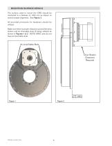
MOUNTING SURFACE DETAILS The surface used to mount the CRD should be machined to a flatness of .050 mm as shown to ensure proper alignment. See Figure 2. All provided provisions for fasteners should be utilized. Make sure there is proper clearance around the drive station and air line/cable slots (if being utilized) as shown in Figures 1 & 2. NOTE: MRO units do not have air line/cable slots. Drive Station Clearance Required
Open the catalog to page 6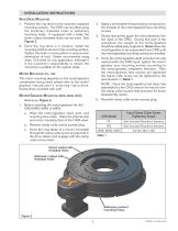
1. Position the ring drive on the customer supplied mounting surface. The CRD can be lifted using the stationary threaded holes or stationary mounting holes. If equipped with a brake the driven output threaded holes can be used. See Figure 3. 2. Once the ring drive is in location, install the mounting bolts to secure to the mounting surface. Tighten the bolts in a star pattern to ensure even distribution of load. Nexen recommends using class 12.9 bolts for any application, although it is the customer’s responsibility to ensure the mounting is suitable for the system loads. Motor Mounting (pl,...
Open the catalog to page 7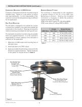
Component Mounting to CRD Output Customer components should be mounted using all available holes. Tighten in a star pattern to ensure even load distribution. It is the responsibility of the customer to ensure the bolt grade and qty is sufficient for the application. Dial Plate Mounting The dial plate is designed to be piloted by a series of dowel pins installed in the plate that straddle the output pilot on the ring drive. Drawings showing this method of piloting are available for each specific size. The dial plates should be mounted using all available holes and supplied fasteners. It is the...
Open the catalog to page 8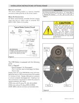
Brake (if equipped) The static holding brake is a factory installed accessory, braking directly on the driven output. Brake Air Connections All Nexen pneumatically actuated devices require clean and dry air, which meet or exceeds ISO 8373.1:2001 Class 4.4.3 quality. Air Supply Typical Brake Control Circuit Gauge Filter Dryer Regulator 3/2 (3 Way) T-n N.C. Valve Quick Exhaust Valve AIR PRESSURE: 8.3 BAR (120 PSI) ABSOLUTE MAX 4.1 BAR (60 PSI) MIN TO ACTUATE 0 BAR (0 PSI) ABSOLUTE MIN The CRD Brake is equipped with the following ports: Refer to Figure 6. - Spring Engaged / Air Disengaged: Port...
Open the catalog to page 9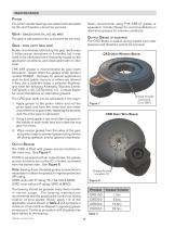
The pinion needle bearings are sealed and lubricated for life, and therefore cannot be serviced. Gear - sealed units (pl, hg, dd, mrs) The gear is lubricated for life, and cannot be serviced. Gear - open units (mrg, mro) Nexen recommends lubricating the gear teeth every 2 million pinion revolutions or 6 months, but it may need to be lubricated more frequently based on the application conditions, and observable tooth or roller wear. THK AFA grease is recommended for gear tooth lubrication. Nexen offers this grease under product number 853901. Greases for special applications such as food grade,...
Open the catalog to page 10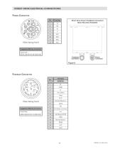
Power Connector Suggested Mating Connector Intercontec BSTA-108-NN-00-08-0036-000 Feedback Connector (View facing front) Suggested Mating Connector Intercontec ASTA-035-NN-00-10-0035-000
Open the catalog to page 11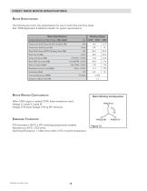
Motor Specifications The following are motor-only specifications for use in motor files and drive setup. See “CRD Application & Selection Guide” for system specifications. Motor Winding Configuration When CRD output is rotated CCW, these waveforms result: Voltage U, Leads V, Leads W Voltage U-W leads Voltage V-W by 60° electrical. Embedded Thermistor PTC thermistor (155°C ± 5°C switching temperature) installed. Resistance at 25°C < 550 ohms. Switching Resistance: > 1330 ohms within ± 5°C of switch temperature.
Open the catalog to page 12All Nexen Group, Inc. catalogs and technical brochures
 PRECISION MOTION CONTROL
56 Pages
 LINEAR MOTION CONTROL
4 Pages
 PRINCIPALS OF OPERATION
1 Page
 Precision in motion.
2 Pages
 Precision Ring Drive
10 Pages
 ECLIPSE PRODUCTS User Manual
14 Pages
 ECLIPSE PRODUCTS
14 Pages
 Linear Couplings
2 Pages
 Eclipse Servo Motor Brake
2 Pages
 Zero Backlash Gear Catalog
30 Pages
 Torque Limiter Catalog
16 Pages
 Servo Brake Catalog
16 Pages
 Rod Lock Catalog
12 Pages
 Rail Brake Catalog
8 Pages
 Indexer Brake Catalog
2 Pages
 Clutch & Brake Catalog
388 Pages


- ERLO load cell
- ERLO coaxial gear reducer
- ERLO clamping
- ERLO tension/compression load cell
- ERLO precision gear reducer
- ERLO strain gauge load cell
- ERLO compact gear reducer
- Solid-shaft gearhead
- Pressure separator filter
- ERLO signal amplifier
- ERLO gear reducer for industrial applications
- Friction brake
- Clamp gearbox
- Basket filter
- Disc brake
- Spring brake
- Friction brake caliper
- Electromagnetic brake
- High load capacity gear reducer
- Automatic filter