- Catalogs
- Newtons4th Ltd.
- PSM/SLM1700 - feature guide
PSM/SLM1700 - feature guide
1 /5Pages

PSM/SLM1700 - feature guide
1 /5Pages
Catalog excerpts

Newtons4th Ltd [email protected] www.newtons4th.com PSM/SLM1700 - feature guide Introduction The modified PSM1700 has been designed to provide SLM functionality plus enhanced generator functions and scope modes that can be achieved with existing PSM hardware. POWER and HARMONIC modes included in the standard PSM instrument have been replaced with SLM and SCOPE modes with corresponding menu options presented by pressing the respective key. In the following pages, we illustrate the basic operating principle of these new modes using a ‘dual sinewave’ mode in the output menu to generate a composite signal of two frequency components. Before proceeding with the examples given below, CH1 and CH2 should be connected to the generator output which can be done using a BNC T-piece and two BCN to BNC cables or the BNC output lead with clips and scope leads for each channel that are provided with the instrument. Quick start The SLM function in the SLM1700 will identify either the single largest or the two largest signals within a specified frequency range. Here we will focus on the ‘dual scan’ SLM mode and to enable the simulation of a dual signal environment, the generator has been equipped with a ‘dual sinewave’ option. From the OUT menu, use the ▼ a nd ► keys to select the dual sinewave mode. In this mode, the generator output will combine two sinewave components that can be controlled in both frequency and amplitude. Numeric values are changed by placing the edit box over the item to be changed, entering numbers from the keypad plus an engineering extension if required then ‘Enter’. Here, a 1kHz repetition frequency is entered with 9 cycles for sinewave 1 and 12 cycles for sinewave 2 resulting in a composite signal comprising 9kHz and 12kHz components. Then, select output and switch to ‘on’. Page 1 of 5
Open the catalog to page 1
Newtons4th Ltd [email protected] www.newtons4th.com Pressing the SCOPE button, the output signal can be seen and the scope mode will have default ‘auto’ trigger. Pressing the SCOPE button again, scope options are presented. From here, the trigger option can be changed to ‘normal’ and after pressing the home key twice, the scope screen will return with a cursor mark (>) on the left axis. Using the ▲ and ▼ keys, the trigger level can be set to the peak of modulation and a stable waveform should be visible. Timebase can be adjusted using the ◄ and ► keys. Pressing the GRAPH button, CH1, CH2...
Open the catalog to page 2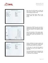
Newtons4th Ltd [email protected] www.newtons4th.com Now press the SLM button to enter the SLM mode and again to see the default mode settings as shown here. Pressing the SLM button again or the HOME button will return to the SLM screen. Pressing the START key will now start a sweep with the steps and frequency range that were entered in the frequency sweep menu. Within the resolution of the sweep steps, the two largest signal components will be marked with cursors and quantified in the left axes. Having identified the largest signals, the frequency 1 and frequency 2 values within the SLM...
Open the catalog to page 3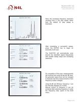
Newtons4th Ltd [email protected] www.newtons4th.com Here, the increased frequency resolution resulting from a 100 step sweep rather than the default 32 step sweep is illustrated. After completing a successful sweep, press the ENTER key to begin an automatic SLM scan. The SLM1700 will automatically scan around the identified signal frequencies with smaller sweep steps and increasing selectivity. On completion of the scan, measurements will continue and using the ▲ and ▼ keys, the generator signal level can be changed to illustrate real time measurements of two frequency locked voltages. Using...
Open the catalog to page 4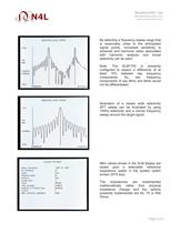
Newtons4th Ltd [email protected] www.newtons4th.com By selecting a frequency sweep range that is reasonably close to the anticipated signal points, increased sensitivity is achieved and harmonic lobes associated with harmonic analysis and broad selectivity can be seen. Note: The SLM1700 is presently configured to expect a difference of at least 15% between two frequency components. So, two frequency components of say 8kHz and 9kHz would not be differentiated. Illustration of a classic wide selectivity DFT sweep can be illustrated by using 100Hz selectivity and a narrow frequency sweep around...
Open the catalog to page 5All Newtons4th Ltd. catalogs and technical brochures
 AC Power Sources
8 Pages
 LCR-Active-Head-IAI2
1 Page
 PPA3500
20 Pages
 Power Measurement
1 Page
 Injection Transformers
1 Page
 PPA1500 ? Compact Power Analyzer
16 Pages
 PPA5500_1500_500 Series Brochure
16 Pages


- Power supply unit
- DC power supply
- AC/DC power supply
- Benchtop analyser
- Switching power supply
- Tabletop power supply
- Digital analyzer
- Compact analyzer
- Variable-output power supply
- Single-phase power supply
- Power amplifying integrated circuit
- Test set
- Power quality analyzer
- Programmable power supply
- Multiple-output power supply
- Sampling analyzer
- Regulated power supply
- High-performance analyzer
- Three-phase power supply
- Electrical network analyzer