PT6314
1 /42Pages
PT6314
1 /42Pages
Catalog excerpts
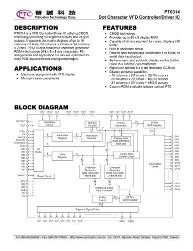
PT6314Dot Character VFD Controller/Driver ICDESCRIPTION FEATURES PT6314 is a VFD Controller/Driver IC utilizing CMOS technology providing 80 segment outputs and 24 grid outputs. It supports dot matrix displays of up to 16 columns x 2 lines, 20 columns x 2 lines or 24 columns x 2 lines. PT6314 also features a character generator ROM which stores 248 x 5 x 8 dos characters. Pin assignments and application circuits are optimized for easy PCB layout and cost saving advantages. • Electronic equipment with VFD display • Microprocessor peripherals CMOS technology Capable of driving segment for cursor displays (48 Built-in oscillation circuit Parallel data input/output (switchable 4 or 8 bits) or serial data input/output Alphanumeric and symbolic display via the built-in ROM (5 x 8 dots): 248 characters Eight user-defined 5 x 8 dot character CGRAM Display contents capability: - 16 columns x 2(1) rows + 32(16) cursors - 20 columns x 2(1) rows + 40(20) cursors - 24 columns x 2(1) rows + 48(24) cursors Custom ROM available (please contact PTC Tel: 886-66296288 • Fax: 886-29174598 • http://www.princeton.com.tw • 2F, 233-1, Baociao Road, Sindian, Taipei 23145, Taiwan
Open the catalog to page 1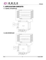
1. APPLICATION CIRCUITS 1.1 SERIAL INTERFACE
Open the catalog to page 3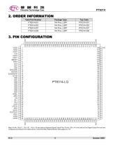
2. ORDER INFORMATION Valid Part Number
Open the catalog to page 5
1. *=N is the Display Line Select Flag in “Function Set” Command 2. Refer to Duty Ratio Setting Section
Open the catalog to page 7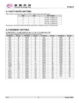
4.1 DUTY RATIO SETTING DS0 and DS1 control the duty ratio of PT6314. Please refer to the table below.
Open the catalog to page 8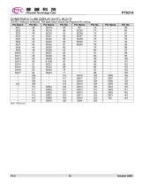
The RL1 setting is irrelevant. The table below shows the Segment Pin setting. Note: *=Not Used
Open the catalog to page 12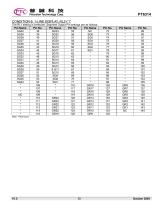
The RL1 setting is irrelevant. Segment Output Pin settings are as follows: Note: *=Not Used
Open the catalog to page 13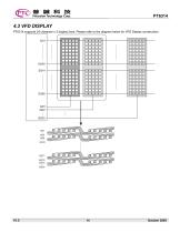
4.3 VFD DISPLAY PT6314 supports 24 character x 2 display lines. Please refer to the diagram below for VFD Display construction.
Open the catalog to page 14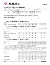
5.2 DISPLAY DATA RAM (DDRAM) The Display Data RAM (DDRAM) stores the display data shown in the 8-bit character codes. When expanded the Display Data RAM supports a capacity of 80 x 8 bits or 80 characters. The area in the DDRAM that is not in used for display may be used as general data RAM. High Order Bits Please note that the DDRAM Address (ADD) is set in the Address Counter(AC) as hexadecimal. Example: DDRAM Address “26”:__ Display Position Digit DDRAM Address(hexadecimal) 5.2.2 N=“0” 1-LINE DISPLAY, LESS THAN 80 CHARACTERS In cases when there are less than 80 display characters, the display...
Open the catalog to page 16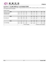
PT6314 5.2.5 N=“1” 2-LINE DISPLAY, 40 CHARACTERS PT6314 can be extended using one of the 16 output extension drivers as GRID. Under this condition, a 40-character x 2 lines display may be constructed. Display Position Digit DDRAM Addre
Open the catalog to page 17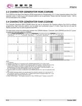
m m m Princeton Technology Corp. 5.3 CHARACTER GENERATOR ROM (CGROM) The CGROM is the Read Only Memory (ROM) responsible for the generation of 5 x 8 dots character patterns from 8-bit character codes. A total of up to 240 character patterns can be generated. Please note that Character Codes -- 00H to 07H are allocated to the CGRAM. The Character Generator RAM (CGRAM) allows the user to reconstruct the character patterns from 8-bit by software programming. Eight character patterns can be written and constructed using 5 x 8 dots. Areas that are not used for display purposes may be used as general...
Open the catalog to page 18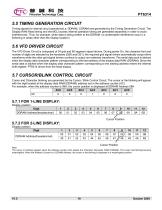
PT63145.5 TIMING GENERATION CIRCUIT Timing signals for internal circuit operations(i.e. DDRAM, CGRAM) are generated by the Timing Generation Circuit. The Display RAM Read timing and the MCU access internal operation timing are generated separately in order to avoid interferences. Thus, for example, when data is being written to the DDRAM, no undesirable interference occur (i.e. flickering in areas other than the display location) The VFD Driver Circuit is composed of 24 grid and 80 segment signal drivers. During power On, the character font and number of digits are selected by the hardware (DS0...
Open the catalog to page 19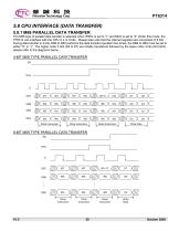
5.8.1 M68 PARALLEL DATA TRANSFER The M68 type of parallel data transfer is selected when IFSEL is set to “1” and MCU is set to “0” Under this mode, the PT6314 can interface with the CPU in 4 or 8 bits . Please take note that the internal registers are composed of 8 bits. During data transfer in 4 bits, DB4 to DB7 performs the data transfer operation two times, the DB0 to DB3 must be set to either “H” or “L”. The higher order 4 bits (D4 to D7) are initially transferred followed by the lower order 4 bits (D0 toD3). please refer to the diagrams below.
Open the catalog to page 20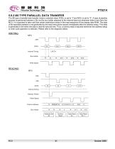
PT6314 5.8.2 i80 TYPE PARALLEL DATA TRANSFER The i80 type of parallel data transfer mode is selected when IFSEL is set to “1”and MCU is set to “0”. A type of pipeline process is performed between LSIs via the bus holder attached to the internal data bus whenever data is sent from the MCU. It is important to take note that certain restrictions exists in the read sequence of this display data RAM. The data of the specified address is not generated by the read instructions issued immediately after the address setup. This data is generated in the when the data is read the second time. Thus, a dummy...
Open the catalog to page 21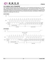
PT6314 5.8.3 SERIAL DATA TRANSFER PT6314 supports serial data transfer mode. When data is written, it can be inputted when the Strobe goes to “0”. The first byte -- Start Byte consists of a total of 8 bits: the Synchronous bits (bit 1 - bit 5), R/W (bit 6), RS (bit 7) and bit 8. The register will be selected (IR or DR) by the RS (bit 7) and the data write or read is selected by R/W (bit 6 = “0”) in this byte. The Start Byte is followed by the 8-bit Instruction Byte. The Start Byte selects which is process is to be inputted first: read the Busy Flag + Address Counter (AC6 to AC0) or read the data...
Open the catalog to page 22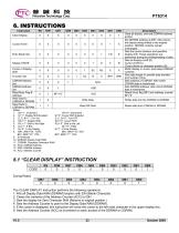
m m m Princeton Technology Corp. 2. S=”1”: Display Shift Enabled I/D=“0”: Decrement S=“0”: Cursor Shift Enabled D, C, B=“0”: Turn OFF S/C=”0”: Cursor Shift R/L=“0”: Shift to the Left DL=“0”: 4 Bits N=“1”: 2-Line Display 10. DDRAM: Display Data RAM 11. CGRAM: Character Generator RAM The CLEAR DISPLAY Instruction performs the following operations: 1. Fills all Display Data RAM (DDRAM) location with 20H (Blank Character). 2. Clears the contents of the Address Counter (ACC) to 00H. 3. Sets the display for Zero Character Shift (Returns to original position.) 4. Sets the Address Counter to point to...
Open the catalog to page 23All NEWHAVEN DISPLAY INTERNATIONAL catalogs and technical brochures
 FT5426G
19 Pages
 FT5336GQQ
13 Pages
 FT5x16
15 Pages
 PT6324
5 Pages
 PT6321
6 Pages
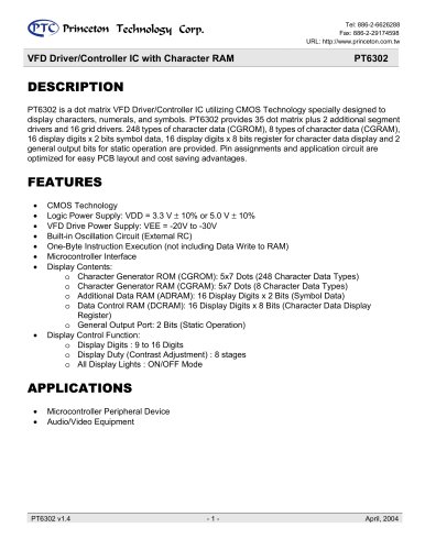 PT6302
43 Pages
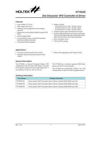 HT16528
40 Pages
 ILI9341V
249 Pages
 ST7735S
201 Pages
 ST7735P3
197 Pages
 EK79202D
78 Pages
 LT6911C
21 Pages
 SSD1306
59 Pages
 SSD1305
70 Pages
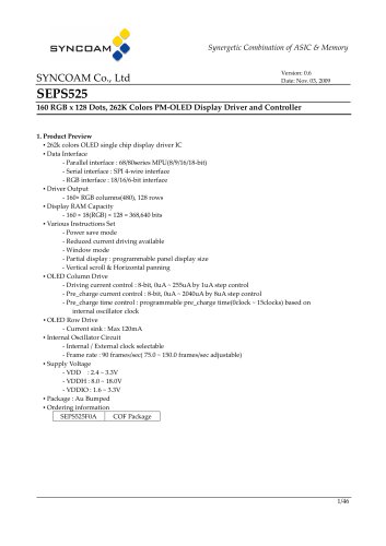 SEPS525
46 Pages
 SEPS114
43 Pages
 SSD1333
36 Pages
 SSD1353
75 Pages
 IST3602
64 Pages
 SSD1333
36 Pages
 SSD1353
75 Pages