


PT6302
PT6302
Catalog excerpts
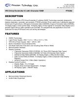
VFD Driver/Controller IC with Character RAM PT6302 is a dot matrix VFD Driver/Controller IC utilizing CMOS Technology specially designed to display characters, numerals, and symbols. PT6302 provides 35 dot matrix plus 2 additional segment drivers and 16 grid drivers. 248 types of character data (CGROM), 8 types of character data (CGRAM), 16 display digits x 2 bits symbol data, 16 display digits x 8 bits register for character data display and 2 general output bits for static operation are provided. Pin assignments and application circuit are optimized for easy PCB layout and cost saving advantages. • CMOS Technology • Logic Power Supply: VDD = 3.3 V ± 10% or 5.0 V ± 10% • VFD Drive Power Supply: VEE = -20V to -30V • Built-in Oscillation Circuit (External RC) • One-Byte Instruction Execution (not including Data Write to RAM) • Microcontroller Interface • Display Contents: o Character Generator ROM (CGROM): 5x7 Dots (248 Character Data Types) o Character Generator RAM (CGRAM): 5x7 Dots (8 Character Data Types) o Additional Data RAM (ADrAm): 16 Display Digits x 2 Bits (Symbol Data) o Data Control RAM (dCrAM): 16 Display Digits x 8 Bits (Character Data Display Register) o General Output Port: 2 Bits (Static Operation) • Display Control Function: o Display Digits : 9 to 16 Digits o Display Duty (Contrast Adjustment) : 8 stages o All Display Lights : ON/OFF Mode • Microcontroller Peripheral Device • Audio/Video Equipment
Open the catalog to page 1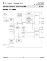
VFD Driver/Controller IC with Character RAM
Open the catalog to page 2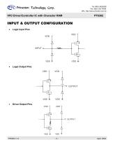
<&> Princeton TecJino1o5^ Corp VFD Driver/Controller IC with Character RAM PT6302 • Logic Input Pins • Logic Output Pins • Driver Output Pins
Open the catalog to page 3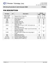
<&> Princeton TecJino1o5^ Corp VFD Driver/Controller IC with Character RAM
Open the catalog to page 4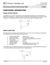
VFD Driver/Controller IC with Character RAM An oscillation circuit may be constructed by connecting external Resistor (R1) and Capacitor (C1) between the oscillator pins -- OSCO and OSCI. The RC time constant depends on the value of VDD voltage used. The target oscillation frequency is 2MHz. Please refer to the diagram below. RESET FUNCTION The Reset Function is enabled when the RSTB Pin is set to "Low" Level. All functions are initialized. The initial status of the various functions is given below: 1. Address of each RAM : Address "00"H 2. Data of each RAM : All contents are undefined. 3. General...
Open the catalog to page 5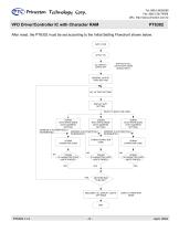
VFD Driver/Controller IC with Character RAM After reset, the PT6302 must be set according to the Initial Setting Flowchart shown below. APPLY VDD STATUS OF ALL OUTPUTS BY RSTB SIGNAL INPUT GENERAL OUTPUT PORT SETTING DISPLAY DUTY SETTING SELECT A RAM TO BE USED DCRAM DATA WRITE MODE (WITH ADDRESS SETTING) ADDRESS IS AUTOMATICALLY INCREMENTED CGRAM DATA WRITE MODE (WITH ADDRESS SETTING) ADDRESS IS AUTOMATICALLY INCREMENTED DCRAM IS CHARACTER CODE WRITE ENDED? ADDRESS IS AUTOMATICALLY INCREMENTED CGRAM CHARACTER CODE DCRAM CHARACTER CODE ADRAM DATA WRITE MODE (WITH ADDRESS SETTING) CGRAM IS CHARACTER...
Open the catalog to page 6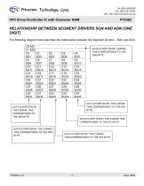
VFD Driver/Controller IC with Character RAM DATA IS WRIITEN BY THE CGRAM THIS CORRESPONDS TO THE 6TH BYTE DATA IS WRITTEN BY THE CGRAM. THIS CORRESPONDS TO THE 2ND BYTE DATA IS WRIITEN BY THE CGRAM THIS CORRESPONDS TO THE 3RD BYTE. DATA IS WRITTEN BY ADRAM. THIS CORRESPONDS TO THE 2ND BYTE DATA IS WRITTEN BY THE CGRAM THIS CORRESPONDS TO THE 5TH BYTE. DATA IS WRITTEN BY THE CGRAM THIS CORRESPONDS TO THE 4TH BYTE
Open the catalog to page 7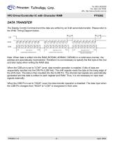
<&> Princeton TecJino1o5^ Corp VFD Driver/Controller IC with Character RAM The Display Control Command and the data are written by an 8-bit serial data transfer. Please refer to the Write Timing Diagram below. FIRST BYTE COMMAND&ADDRESS DATA SECOND BYTE CHARACTER CODE DATA SECOND BYTE CHARACTER CODE DATA OF THE NEXTADDRESS Note: When data is written into the RAM (DCRAM, ADRAM, CGRAM) in a continuous manner, the address are automatically incremented. Therefore it is not necessary to specify the first byte of the 2nd and later bytes when writing the RAM data. When the CSB pin is set to "LOW" Level,...
Open the catalog to page 8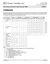
<&> Princeton TecJino1o5^ Corp VFD Driver/Controller IC with Character RAM The following are the list of commands issued by PT6302. When data is written into the RAM (DCRAM, CGRAM, or ADRAM) in a continuous manner, the addresses are automatically incremented internally. It is therefore not necessary to specify the first byte. 1. The Test Mode is not a user function, but an IC internal function 5. Pn = General Output Port Status Bit, n = 1 to 2
Open the catalog to page 9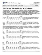
<&> Princeton TecJino1o5^ Corp VFD Driver/Controller IC with Character RAM The DCRAM Data Write Command is used to specify the address of the DCRAM and writes the character code of the CGROM and CGRAM. The DCRAM consists of 4 address bits which are used to store the CGRAM & CGROM character codes. The character codes specified by the DCRAM is converted to a 5 x 7 dot matrix character pattern via the CGROM and CGRAM. The DCRAM can store up to 16 characters. The DCRAM Data Write Command Format is shown below. Character Code of CGRAM & CGROM are specified and rewritten into the DCRAM Address 0 H.
Open the catalog to page 10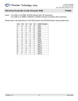
<&> Princeton TecJino1o5^ CorpVFD Driver/Controller IC with Character RAM where: X0 (LSB) to X3 (MSB): DCRAM Address Bits (16 Characters) C0 (LSB) to C7 (MSB): CGROM & CGRAM Character Code Bits (256 Characters) Please refer to the table below for the GRID position and DCRAM Address setting relationship.
Open the catalog to page 11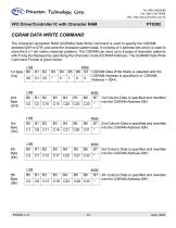
<&> Princeton TecJino1o5^ Corp VFD Driver/Controller IC with Character RAM The Character Generator RAM (CGRAM) Data Write Command is used to specify the CGRAM address (00H to 07H) and write the character pattern data. It consists of 3 address bits which is used to store the 5 x 7 dot matrix character patterns. The CGRAM can store up to 8 types of character patterns which may be displayed by specifying the Character Code (DCRAM Address). The CGRAM Data Write Command Format is given below. 1st Column Data is specified and rewritten into the CGRAM Address 00H. 2nd Column Data is specified and rewritten...
Open the catalog to page 12All NEWHAVEN DISPLAY INTERNATIONAL catalogs and technical brochures
 FT5426G
19 Pages
 FT5336GQQ
13 Pages
 FT5x16
15 Pages
 PT6324
5 Pages
 PT6321
6 Pages
 PT6314
42 Pages
 HT16528
40 Pages
 ILI9341V
249 Pages
 ST7735S
201 Pages
 ST7735P3
197 Pages
 EK79202D
78 Pages
 LT6911C
21 Pages
 SSD1306
59 Pages
 SSD1305
70 Pages
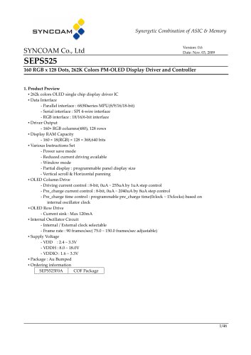 SEPS525
46 Pages
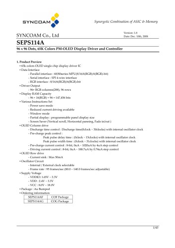 SEPS114
43 Pages
 SSD1333
36 Pages
 SSD1353
75 Pages
 IST3602
64 Pages
 SSD1333
36 Pages
 SSD1353
75 Pages