FT5x16
1 /15Pages
FT5x16
1 /15Pages
Catalog excerpts

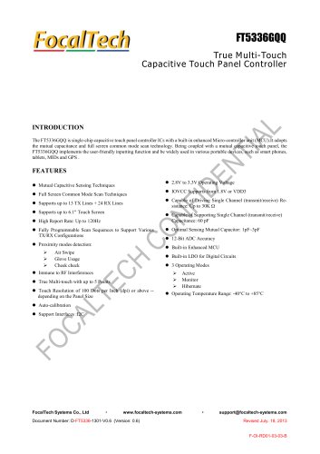
True Multi-Touch Capacitive Touch Panel Controller INTRODUCTION The FT5X16 is single-chip capacitive touch panel controllers with built-in enhanced Micro-controller unit (MCU). It provides the benefits of full screen common mode scan technology,fast response time and high level of accuracy.It can drive capacitive type touch panel with up to 26 driving and 16 sensing lines. • Mutual Capacitive Sensing Techniques • High immunity to inductive power noise • Automatic mode switching (Active, Monitor,Sleep) • Support >100Hz sampling rate > IOVCC supports from 1.8V to 3.6V • Single Channel(TX or RX)resistance: Q • Single Channel (transmit / receive) C : 40pF • Features “short I/O ” testing for sense pins • Supports various type of panels with no ground shielding layer FocalTech Systems Co., Ltd • www.focaltech-systems.com • [email protected]
Open the catalog to page 1
THIS DOCUMENT CONTAINS INFORMATION PROPRIETARY TO FOCALTECH SYSTEMS CO.,LTD., AND MAY NOT BE REPRODUCED, DISCLOSED OR USED IN WHOLE OR PART WITHOUT THE EXPRESS WRITTEN PERMISSION OF FOCALTECH SYSTEMS CO.,LTD. Copyright © 2014, FocalTech Systems CO.,Ltd .All rights reserved Version1.1︱Page2 of 15
Open the catalog to page 2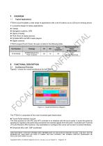
FT5X16 accommodates a wide range of applications with a set of buttons up to a 2D touch sensing device. It ‘s powerful design for below applications. • Game consoles • POS (Point of Sales) devices • Portable MP3 and MP4 media players • Digital cameras FT5X16 supportTouch Panel, the spec is listed in the following table, 2 FUNCTIONAL DESCRIPTION 2.1 Architectural Overview Figure2-1 shows the overall architecture for theFT5X16. The FT5X16 is comprised of five main functional parts listed below, • Touch Panel Interface Circuits The main function for the AFE and AFE controller is to interface with...
Open the catalog to page 3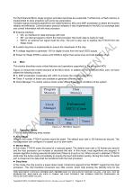
For the Enhanced MCU, larger program and data memories are supported. Furthermore, a Flash memory is implemented to store programs and some key parameters. Complex signal processing algorithms are implemented by MCU and DSP accelerator to detect the touches reliably and efficiently. Communication protocol software is also implemented in this MCU to exchange data and control information with the host processor. External Interface I2C: an interface for data exchange with host INT: an interrupt signal to inform the host processor that touch data is ready for read RSTN: an external low signal...
Open the catalog to page 4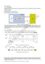
Host Interface Figure 2-3shows the interface between a host processor and FT5X16. This interface consists of the following three sets of signals: Serial Interface Interrupt from FT5X16 to the Host Reset Signal from the Host to FT5X16 Figure 2-3 Host Interface Diagram The serial interfaceofFT5X16 is I2C. The detail of the interface is described in detail in Section 2.5. The interrupt signal (/INT) is used for FT5X16 to inform the host that data are ready for the host to receive. The /RST signal is used for the host to wake up FT5X16 from the Sleep mode. After resetting, FT5X16 shall enter...
Open the catalog to page 5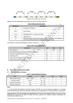
Figure 2-6 I2C master read, slave write Table 2-1 lists the meanings of the mnemonics used in the above figures. Table 2-1Mnemonics Description Mnemonics S Description I2C Start or I2C Restart Slave address READ/WRITE bit, ‘1’ for read, ‘0’for write STOP: the indication of the end of a packet (if this bit is missing, S will indicate the end of the current packet and the beginning of the next packet) I2C Interface Timing Characteristics is shown in Table 2-2. Table 2-2 I2C Timing Characteristics Parameter Bus free time between a STOP and START condition Hold time (repeated) START condition Data...
Open the catalog to page 6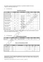
Input high-level voltage Input low -level voltage Output high -level voltage Output low -level voltage Current consumption (Normal operation mode) Current consumption (Monitor mode) Current consumption (Sleep mode) Step-up output voltage Power Supply voltage Notes: This consumption ticular sensor design and data is intended for de firmware options. Max. guidance only. Actual current will depend on the par- 3.3 AC Characteristics THIS DOCUMENT CONTAINS INFORMATION PROPRIETARY TO FOCALTECH SYSTEMS CO.,LTD., AND MAY NOT BE REPRODUCED, DISCLOSED OR USED IN WHOLE OR PART WITHOUT THE EXPRESS WRITTEN...
Open the catalog to page 7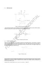
Figure 3-1General PurposeIn/Out Port Circuit. The input/output property can be configured via firmware setting. The firmware can also control its output behavior as push-pull or as open-drain that SDA of I2C interface is required. Figure 3-2 Reset Input Port Circuits POWER ON/Reset Sequence Reset should be pulled down to be low before powering on and powering down. I2C shouldn’t be used by other devices during Reset time after VDD powering on (Trtp). INT signal will be sent to the host after initializing all parameters and then start to report points to the host. If Power is down, the voltage...
Open the catalog to page 8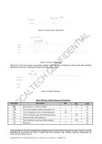
Figure 3-4 Power Cycle requirement Trtp Tvdr Tvdr Tpon VDD Reset INT I2C Figure 3-5 Power on Sequence Reset time must be enough to guarantee reliable reset, the time of starting to report point after resetting approach to the time of starting to report point after powering on. Trsi Figure 3-6 Reset Sequence Table 3-5Power on/Reset Sequence Parameters Parameter Rise time from 0.1VDD to 0.9VDD Time of the voltage of supply being below 0.3V Time of resetting to be low before powering on Time of starting to report point after powering on Reset time after VDD powering on Time of starting to report...
Open the catalog to page 9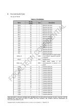
PIN CONFIGURATIONS Pin List of FT5X16 Table 4-1 Pin Definition Name Receiver input pins Receiver input pins Receiver input pins Receiver input pins Receiver input pins Receiver input pins Receiver input pins Receiver input pins Receiver input pins Receiver input pins Receiver input pins Receiver input pins Receiver input pins Receiver input pins Receiver input pins Receiver input pins internal generated 5V power supply, A 1μF ceramic capacitor to ground is required. Analog ground digital ceramiccapacitor to ground is required. THIS DOCUMENT CONTAINS INFORMATION PROPRIETARY TO FOCALTECH SYSTEMS...
Open the catalog to page 10All NEWHAVEN DISPLAY INTERNATIONAL catalogs and technical brochures
 FT5426G
19 Pages
 FT5336GQQ
13 Pages
 PT6324
5 Pages
 PT6321
6 Pages
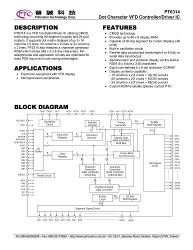 PT6314
42 Pages
 PT6302
43 Pages
 HT16528
40 Pages
 ILI9341V
249 Pages
 ST7735S
201 Pages
 ST7735P3
197 Pages
 EK79202D
78 Pages
 LT6911C
21 Pages
 SSD1306
59 Pages
 SSD1305
70 Pages
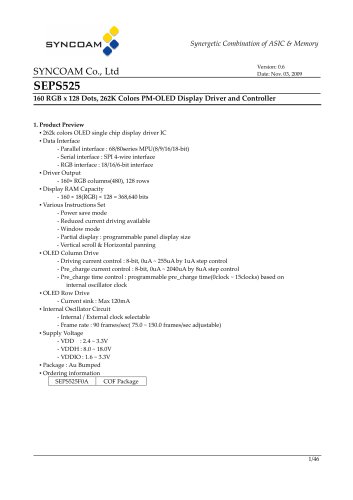 SEPS525
46 Pages
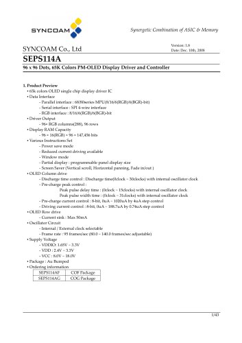 SEPS114
43 Pages
 SSD1333
36 Pages
 SSD1353
75 Pages
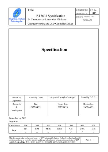 IST3602
64 Pages
 SSD1333
36 Pages
 SSD1353
75 Pages