DP700 Digital Readout
1 /34Pages

DP700 Digital Readout
1 /34Pages
Catalog excerpts
User Manual
Open the catalog to page 1
Contents Specification Electrical Physical Environment Accreditation Disposal Input and Resolution Page 3 Page 3 Page 3 Page 3 Page 3 Page 3 Page 3 Mounting Options Mill Mount Lathe Mount Adjustable Mount Panel Mount Page 4 Page 4 Page 4 Page 4 Page 4 Connection Details Important Information Connections Page 5 Page 5 Page 5 Display and Keypad Understanding the Display Understanding the Keypad Page 6 Page 6 Page 6 Setting up the Unit Navigating Complete Setup Navigating Complete Setup (Continued) Language Setup Type Setup Encoder Type Setup Encoder Resolution Setup Direction of Travel Setup Radius...
Open the catalog to page 2
Specification Electrical EU Directive 73/23/EEC (Low Voltage Directive) BS EN 55022:1998 Class B BS EN 55024:1998 Input to Power Supply Unit (Supplied) 100-240V (47-63Hz) External switch-mode - Output voltage 15VDC Input Voltage to DP700 15-24VDC ±10% Conforms to Low Voltage Directive Physical Height Width Depth Weight Environmental Climatic Range Storage Temperature Working Temperature Working Humidity IP-Ingress Protection IP54 Panel Mount IP40 Stand Alone Accreditation CE Disposal At the end of its life, you should dispose of the DP700 system in a safe manner applicable to electrical goods...
Open the catalog to page 3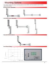
Mounting Options This chapter details the various mounting options for the DP700, both the standard version and the panel mount version. Mill Mount (Non Adjustable) Lathe Mount (Non Adjustable) Adjustable Mount Options Panel Mount Option Panel Panel cut Cutout Det out 250.00 Fixing Ctrs.
Open the catalog to page 4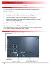
Connection Details This chapter details the cable connections for the DP700. Important Details You can only use the DP700 with Newall Spherosyn and Microsyn analogue encoders. You need to ensure that: You secure all the cables to prevent the connectors from dropping into hazardous positions (for example the floor or coolant tray) when you unplug them. You route all cables to prevent them from being caught on moving parts. The DP700 is grounded to the machine, using the braided grounding lead provided, before you turn on the machine supply. The power has been disconnected, before you connect the...
Open the catalog to page 5
Display and Keypad This chapter explains how to interpret the display and use the keypad. Understanding The Display Feed Rate Display: mm per second for mm mode, inches per minute for inch mode Message Display Understanding The Keypad Axis Selection Key Digifind / Reference Switches between Zero and Axis Preset modes Numeric Keys Switches between Absolute and Incremental modes Switches between Inch and mm display Clear Numeric Entry Centre Find Undo Key Information selection (scrolls through options on Message display) Function Menu Key Function Navigation Keys
Open the catalog to page 6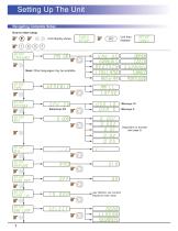
Setting Up The Unit Navigating Complete Setup How to enter setup Until display shows setup language Note: Other languages may be available setup type setup encoder setup res funcs setup Unit then displays Eng us francais deutsch italiano russian dansk czech espanol turkce portugue setup measure setup code? user defined, use numeric keypad to enter value none linear segments Dependant on encoder (see page 2)
Open the catalog to page 7
Setting Up The Unit Navigating Complete Setup (continued) Only applicable to 3 axes units setup plane setup funcs setup beep setup sleep off user defined, use numeric keypad to enter value (value is in whole minutes) setup reset reset as To exit setup
Open the catalog to page 8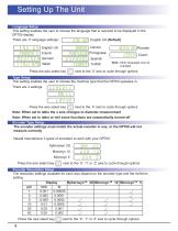
Setting Up The Unit Language Setup This setting enables the user to choose the language that is required to be displayed in the DP700 display. There are 11 language settings: Eng gb English UK (Default) Eng us francais deutsch italiano English US French German Italian dansk Danish portugue Portuguese e s p a n o l Spanish turkce Turkish Press the axis select key russian czech Russian Czech Note: Other languages may be t available next to the ‘X’ axis to cycle through options Type Setup This setting enables the user to choose the machine type that the DP700 operates in. There are 3 settings: Press...
Open the catalog to page 9
Setting Up The Unit Direction of Travel Setup You use the direction setting to match the DP700 to the actual direction of travel of any axis. There are two settings for each axis Press the axis select key next to the ‘X’, ‘Y’ or ‘Z’ axis to cycle through options Example If the current setting is the setting to and the travel is positive from right to left, changing will reverse the direction to measure positive from left to right. Radius / Diameter (measure Setup) The radius/diameter function allows the operator to display actual (radius) or twice-actual (diameter) measurements for each axis....
Open the catalog to page 10
Setting Up The Unit Error Compensation Your digital readout (DRO) system helps you to improve productivity. It decreases the number of scrapped parts, as you no longer have to be concerned about making mistakes related to counting the revolutions on the dials. Your DRO system also helps to eliminate some errors related to ballscrew backlash. Your DRO system will operate to its published accuracy, provided all components are in working order and properly installed. Field calibration is not necessary. Accuracy problems with machined parts may be caused by machine error, DRO system error, or a combination...
Open the catalog to page 11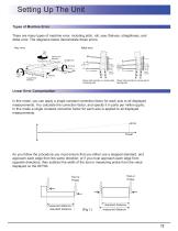
Setting Up The Unit Types of Machine Error There are many types of machine error, including pitch, roll, yaw, flatness, straightness, and Abbé error. The diagrams below demonstrate these errors. Abbé error Roll Axis Travel Pitch Axis greater than Linear encoder less than encoder A2 Linear encoder Flatness Typical Pitch Deviation Shown with encoder on concave side of bearing path Shown with encoder on convex side of bearing path Linear Error Compensation In this mode, you can apply a single constant correction factor for each axis to all displayed measurements. You calculate the correction factor,...
Open the catalog to page 12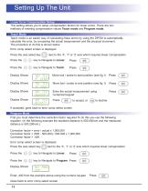
Setting Up The Unit Linear Error Compensation Setup This setting allows you to setup compensation factors for linear errors. There are two methods of entering compensation values Teach mode and Program mode. Teach Mode Teach mode is an easier way of calculating linear errors by using the DP700 to automatically calculate the error, by comparing the actual measurement and the physical movement. The procedure to do this is shown below. Error comp select screen is displayed Press the axis select key next to the ‘X’, ‘Y’ or ‘Z’ axis which requires linear compensation Move tool / probe to start position...
Open the catalog to page 13All NEWALL catalogs and technical brochures
 SHG-A2 Linear Encoder
5 Pages
 DP700 Data Sheet
2 Pages
 Linear Encoder Brochure
15 Pages
 DP1200 Data Sheet
1 Page
 Corus Case Study
2 Pages
 Digital Readout Systems
7 Pages


Archived catalogs
 Linear Encoder Brochure
15 Pages

- Angular encoder
- Incremental encoder
- Incremental rotary encoder
- DC rotary encoder
- Stainless steel rotary encoder
- 5VDC rotary encoder
- Incremental linear encoder
- 24VDC rotary encoder
- Magnetic linear encoder
- 12VDC rotary encoder
- 15VDC rotary encoder
- Standard rotary encoder
- Absolute linear encoder
- Optical linear encoder
- 8VDC rotary encoder
- High-accuracy linear encoder
- 9VDC rotary encoder
- IP67 linear encoder
- Sealed linear encoder