- Catalogs
- Neptune Chemical Pump
- Glycol Feeder
Glycol Feeder
1 /15Pages

Glycol Feeder
1 /15Pages
Catalog excerpts
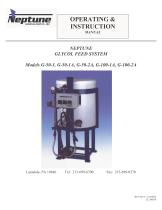
OPERATING & INSTRUCTION MANUAL NEPTUNE GLYCOL FEED SYSTEM Models G-50-1, G-50-1A, G-50-2A, G-100-1A, G-100-2A
Open the catalog to page 1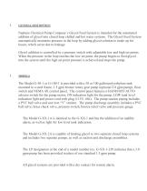
GENERAL DESCRIPTION Neptune Chemical Pump Company’s Glycol Feed System is intended for the automated addition of glycol into closed loop chilled and hot water systems. The Glycol Feed System automatically maintains pressure in the loop by adding glycol solution to make up for losses, which occur due to leakage. Glycol addition is controlled by a pressure switch with adjustable low and high set points. When the pressure in the loop reaches the low set point, the pump begins to feed glycol into the system until the high set point pressure is achieved and stops the pump. The Model G-50-1 or G-100-1...
Open the catalog to page 2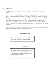
The glycol feeder is provided with a control panel with HAND/OFF/AUTO selector switch. When the panel is switched to the AUTO position, the pump is actuated via the pressure switch, which is mounted in the discharge assembly and sensing the pressure in the loop. The pressure switch is pre-set to start the pump at 12 psi and stop the pump when 30 psi in the loop is achieved. The adjustment range for the standard pressure switch is 10-45 psi to start the pump and 20-60 psi to stop the pump. The minimum differential pressure between the cut in and cut out set points is 10 psi and the maximum is...
Open the catalog to page 3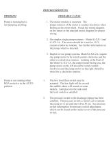
TROUBLESHOOTING PROBLEM PROBABLE CAUSE Pump is running but is not pumping anything 1. The motor rotation is incorrect. The proper rotation of the motor is counter-clockwise when looking at the motor shaft. Check the wiring diagram on the motor or the attached motor diagram for proper wiring. 2. On simplex single pump systems – Model G-XX-1 and G-XX-1A. The motor should be wired for 115V counter-clockwise rotation. See further information on the pump, which is attached. 3. Duplex or two pump systems, Model G-XX-2A, require one pump motor to be wired counter-clockwise and the other in a clockwise...
Open the catalog to page 4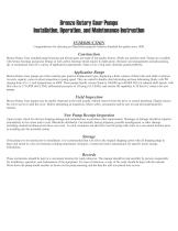
Bronze Rotary Gear Pumps Installation, Operation, and Maintenance Instruction INTRODUCTION Congratulations for choosing an Oberdorfer pump,the Industry Standard for quality since 1890. Construction Bronze Rotary Gear standard pump housings and helical gears are made of top quality bronze. Shafts are stainless steel. Pumps are available with bronze bearings and grease fittings or with carbon bearings which require no lubrication. Dynamic seal arrangements include packing, lip, or mechanical seals for a variety of application requirements. Static cover o-ring seals eliminate gasket problems. Application...
Open the catalog to page 8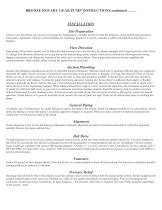
BRONZE ROTARY GEAR PUMP INSTRUCTIONS continued ……. INSTALLATION Site Preparation Choose a site that allows easy access to the pump for maintenance. Consider protection from the elements. Guard against drips and spray from nearby equipment. Choose a solid foundation for mounting. If noise is a concern, consider a rubber pad under the pump base to dampen. Flow Direction Gear pumps will perform equally well in either direction however care must be taken for pumps equipped with integral pressure relief valves. To change flow direction effectively reversing the suction and discharge ports, simply...
Open the catalog to page 9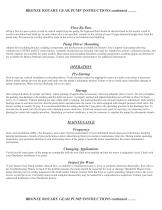
BRONZE ROTARY GEAR PUMP INSTRUCTIONS continued ……. Flow By-Pass When a flow by-pass system is used to control output from the pump, the bypassed fluid should be directed back to the suction vessel to avoid recirculation heat build-up. In cases where this is not possible, connect to the suction at least 10 pipe diameters length away from the pump inlet. Provisions for cooling should be made in the event of recirculation heat build-up. Pump Driver Mounting Adapter kits (including bracket, coupling components, and hardware) are available for Bronze Close Coupled Gear pumps allowing connectivity...
Open the catalog to page 10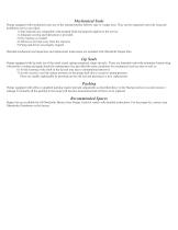
Mechanical Seals Pumps equipped with mechanical seals are of the standard pusher bellows type or wedge style. They can be expected to provide long and troublefree service provided: 1) Seal materials are compatible with pumped fluid and properly applied to the service. 2) Adequate cooling and lubrication is provided 3) Dry running is avoided 4) Abrasives are kept away from the seal area 5) Pump and driver are properly aligned Detailed mechanical seal inspection and replacement instructions are included with Oberdorfer Repair Kits. Lip Seals Pumps equipped with lip seals are of the metal cased,...
Open the catalog to page 11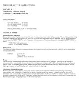
PRESSURE SWITCH INSTRUCTIONS SQUARE D Commercial Pressure Switch Class 9013, Model FSG29J99 Model FSG29J99 CUT-OUT RANGE 20-60 PSI ADJUSTABLE RANGE 10-30 PSI CUT-IN RANGE 10-45 PSI PRESSURE CONNECTION : ¼” NPT EXTERNAL TECHNICAL TERMS Operating Points (Settings) Every pressure switch has two operating points; one on rising pressure and one of falling pressure. The operating point on rising pressure is referred to as the TRIP POINT or cut out for pumps and compressors and the operating point on falling pressure is referred to as the RESET POINT or cut in for pumps and compressors. These operating...
Open the catalog to page 12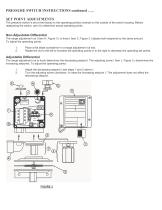
PRESSURE SWITCH INSTRUCTIONS continued ….. SET POINT ADJUSTMENTS The pressure switch is set at the factory to the operating point(s) marked on the outside of the switch housing. Before readjusting the switch, cyle it to determine actual operating points. Non-Adjustable Differential The range adjustment nut ( Item H, Figure 3 ) or knob ( Item C, Figure 3 ) adjusts both setpoints by the same amount. To adjust the operating points : 1. 2. Place a flat blade screwdriver in a range adjustment nut slot. Rotate the nut to the left to increase the operating points or to the right to decrease the operating...
Open the catalog to page 13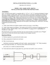
INSTALLATION INSTRUCTIONS LL-3 (L-30N) LIQUID LEVEL SWITCH MODEL L30N LIQUID LEVEL SWITCH INSTALLATION AND OPERATING INSTRUCTIONS Installation: The L-30 liquid level switch is supplied with a 1-1/2” or 1-1/4” X 1 bushing threaded in place with 2 to 3 wraps of teflon tape, which must be intact or renewed if bushing and switch are separated before assembly in tank. Care must be exercised when threading the bushing into plastic or metal fittings. Apply a minimurn of 2 to a maximum of 3 wraps of teflon tape to threads of bushing - this is especially important if unit is to be used in metal fittings...
Open the catalog to page 14All Neptune Chemical Pump catalogs and technical brochures
 Sample Coolers
2 Pages
 Calibration Columns
2 Pages
 Pulsation Dampeners
2 Pages
 Mixer Catalog
12 Pages
 Neptune Solar D? Pump Series
2 Pages
 Series PZ Pumps
10 Pages
 Polymaster
8 Pages
 By-Pass & Filter Feeder
2 Pages
 Neptune Brochure
20 Pages


- AMOT industrial pump
- AMOT electric pump
- AMOT stationary pump
- AMOT water pump
- AMOT chemical pump
- AMOT lubricant pump
- AMOT dynamic mixer
- AMOT oil pump
- AMOT pump for the chemical industry
- Diaphragm pump
- Batch agitator
- Metering pump
- AMOT 380 V pump
- AMOT liquid mixer
- AMOT volumetric dosing dispenser
- AMOT waterproof pump
- HDPE pump
- Vertical homogenizer