
- Catalogs
- NEOTON MOTOR
- ACSDP100S-40_datasheet.pdf


- Company
- Products
- Catalogs
- News & Trends
- Exhibitions
ACSDP100S-40_datasheet.pdf
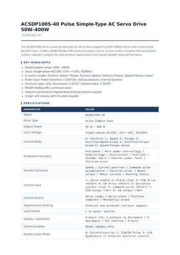
ACSDP100S-40_datasheet.pdf
- Output Power Range: 50W – 400W
- Input: Single-phase AC220V -15%~+10%, 50/60Hz
- Control Modes: Position, Speed, Torque, Position+Speed, Position+Torque, Speed+Torque mixed
- Pulse Input Options: Pulse+Direction, CCW-CW, A/B Quadrature, Internal position
- Electronic Gear Ratio: Numerator 1–32767 / Denominator 1–32767
- Communication: RS485 Modbus RTU
- Regenerative Braking: Supports internal and external resistors
- Display: 5-digit LED with 4-button keypad
- Model: ACSDP100S-40
- Drive Type: Pulse Simple-Type
- Protection Functions: Overspeed, Main power overvoltage, Undervoltage, Overcurrent, Overload, Encoder fault, Control power fault, Position error
- Monitor Functions: Speed, Current position, Command pulse accumulation, Position error, Motor torque, Motor current, Running status
- Control Inputs: Servo enable, Alarm clear, CCW drive inhibit, CW drive inhibit, Deviation counter clear, Command pulse inhibit, CCW torque limit, CW torque limit
- Control Outputs: Servo ready, Servo alarm, Position complete, Mechanical brake
- Load Inertia: ≤ 3× motor inertia
- Dimensions: 41 × 159.5 × 158.5 mm
- Mounting Depth: 158.8 mm
- DIN Rail Width: 38 mm
- CN1: Control signal input/output connector (DB26 Male)
- CN2: Encoder signal connector (DB15 Female)
- CN3 / CN4: Communication connectors (RJ45 for RS485)
- L1, L2: Main power input terminals
- P, D, C, N: Dynamic braking resistor connection terminals
- U, V, W: Servo motor output terminals
- PE: Protective earth terminal
- CN1 Pins: Include COM+, Servo ON, Alarm reset, Positioning complete, Position command pulse input, Pulse input direction, Positive/Negative overtravel, Brake output, Zero-speed output, Torque limit output, Alarm output
- CN2 Pins: Include Encoder power, A/B/Z/U/V/W phase inputs, Encoder frame ground
Catalog excerpts
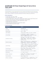
ACSDP100S-40 Pulse Simple-Type AC Servo Drive 50W–400W ACSDP100S-40 The ACSDP100S-40 is a pulse simple-type AC servo drive supporting 50W–400W motors with single-phase AC220V input. It offers RS485 Modbus RTU communication and six control modes including internal position control, making it suitable for cost-sensitive applications that require reliable servo performance. KEY HIGHLIGHTS Output power range: 50W – 400W Input: Single-phase AC220V -15%~+10%, 50/60Hz 6 control modes: Position, Speed, Torque, Position+Speed, Position+Torque, Speed+Torque mixed Pulse input: Pulse+Direction / CCW-CW / A/B Quadrature / Internal position Electronic gear ratio: Numerator 1–32767 / Denominator 1–32767 RS485 Modbus RTU communication Internal and external regenerative braking resistor support 5-digit LED display with 4-button keypad SPECIFICATIONS PARAMETER Drive Type Pulse Simple-Type Output Power Input Voltage Control Mode 0: Position 1: Speed 2: Torque 3: Position+Speed mixed 4: Position+Torque mixed 5: Speed+Torque mixed Protection Functions Overspeed / Main power overvoltage / Undervoltage / Overcurrent / Overload / Encoder fault / Control power fault / Position error Monitor Functions Speed / Current position / Command pulse accumulation / Position error / Motor torque / Motor current / Running status Control Input 1: Servo enable 2: Alarm clear 3: CCW drive inhibit 4: CW drive inhibit 5: Deviation counter clear 6: Command pulse inhibit 7: CCW torque limit 8: CW torque limit Control Output Servo ready / Servo alarm / Position complete / Mechanical brake Regenerative Braking Internal and external resistor support Load Inertia Display / Operation 5-digit LED, 4 buttons (▲ Increment / ▼ Decrement / SET Confirm / ◄ Exit) Position Input Mode 0: Pulse+Direction 1: CCW/CW Pulse 2: A/B Quadrature 3: Interna
Open the catalog to page 1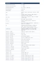
Electronic Gear Numerator Electronic Gear Denominator Dimensions (W×H×D) Mounting Depth Control signal input/output connector (DB26 Male) Encoder signal connector (DB15 Female) — connected to motor encoder Communication connectors (RJ45, for RS485 crystal head) Main power input terminals Dynamic braking resistor connection terminals Servo motor output terminals — connect to motor U, V, W phases Protective earth terminal — connect to power supply ground and motor ground Bus capacitor charge indicator. LED on = capacitor charged. Do not touch power terminals while LED is on, even after power-off....
Open the catalog to page 2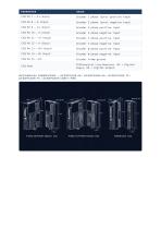
CN2 Pin 7 — Z+ (Input) CN2 Pin 8 — Z- (Input) CN2 Pin 9 — U+ (Input) CN2 Pin 10 — U- (Input) CN2 Pin 11 — V+ (Input) CN2 Pin 12 — V- (Input) CN2 Pin 13 — W+ (Input) CN2 Pin 14 — W- (Input) Encoder Z phase (zero) positive input Encoder Z phase (zero) negative input Encoder U phase positive input Encoder U phase negative input Encoder V phase positive input Encoder V phase negative input Encoder W phase positive input Encoder W phase negative input Encoder frame ground Differential Line Receiver. DI = Digital Input, DO = Digital Output.
Open the catalog to page 3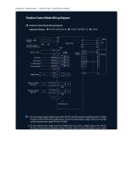
WIRING DIAGRAM — POSITION CONTROL MODE Note: P200H supports three-phase 220VAC input Alarm Reset Digital Output Position Command Pulse (5V) Position Command Sign (SV) Chassis Ground 1. The input power suppfy voltage range is 20V-28V DCfand the maximum operating current is 100mA. If using an external 24V power supply, please connect the external power supply +24V to pin 16 (COM), and the external power supply 0V to pin 43 (EOV). 2. The DO output power supply must be provided by the user, with a voltage range of 5V~24V DC. The DO terminal maximum allowable voltage is DC30V, and the maximum allowable...
Open the catalog to page 4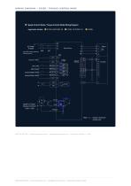
• Speed Control Mode / Torque Control Mode Wiring DiagramApplicable Models: © P100S-40/P100H-40 © PI00S-75/P1OOH-75 © P200H NEOTON MOTOR | www.neotonmotor.com | [email protected] | Generated October 2, 2026 NEOTON MOTOR | www.neotonmotor.com | [email protected] | Generated October 2, 2026
Open the catalog to page 5All NEOTON MOTOR catalogs and technical brochures
 BLAR-090140-MH_datasheet.pdf
4 Pages
 BLAR-090100-MH_datasheet.pdf
4 Pages
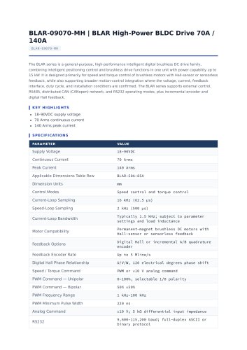 BLAR-09070-MH_datasheet.pdf
4 Pages
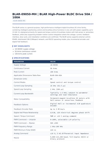 BLAR-09050-MH_datasheet.pdf
4 Pages
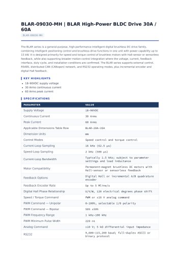 BLAR-09030-MH_datasheet.pdf
4 Pages
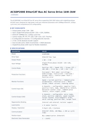 ACSDP200E_datasheet.pdf
4 Pages
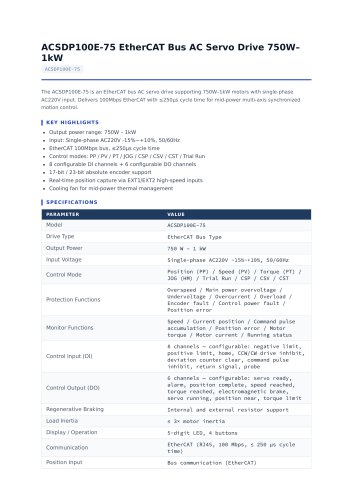 ACSDP100E-75_datasheet.pdf
4 Pages
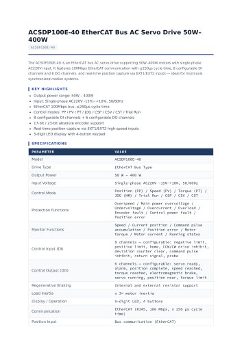 ACSDP100E-40_datasheet.pdf
4 Pages
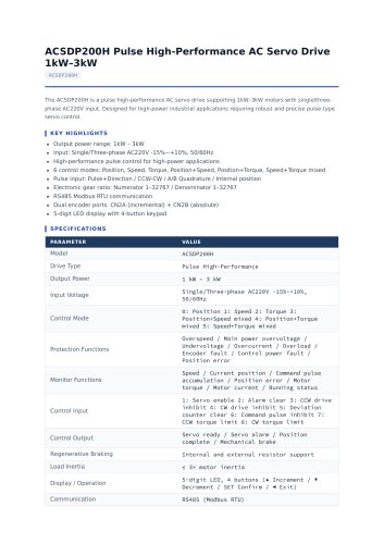 ACSDP200H_datasheet.pdf
5 Pages
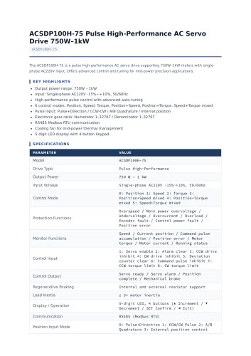 ACSDP100H-75_datasheet.pdf
5 Pages
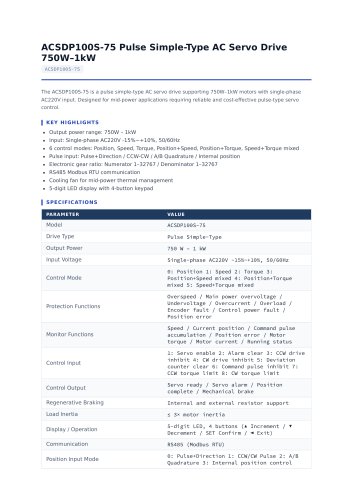 ACSDP100S-75_datasheet.pdf
5 Pages
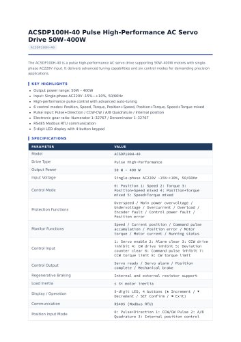 ACSDP100H-40_datasheet.pdf
5 Pages
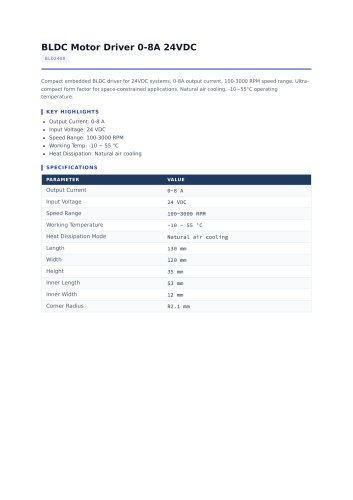 BLD2408_datasheet.pdf
2 Pages
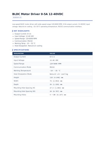 BLD510-LS_datasheet.pdf
2 Pages
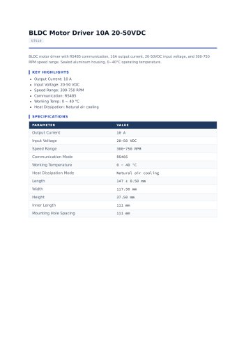 GT510_datasheet.pdf
2 Pages
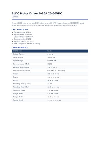 BLD510_datasheet.pdf
2 Pages
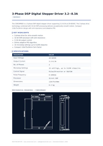 CWD3M683_datasheet.pdf
1 Page
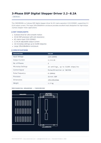 CWD3M208_datasheet.pdf
1 Page
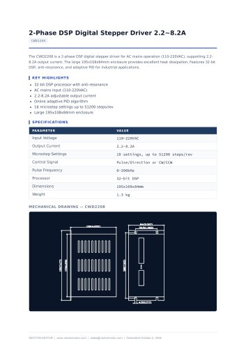 CWD2208_datasheet.pdf
1 Page
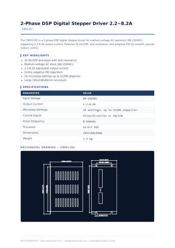 CWD1182_datasheet.pdf
1 Page
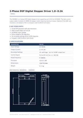 CWD882_datasheet.pdf
1 Page
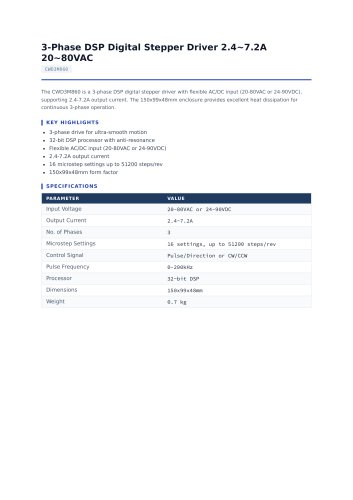 CWD3M860_datasheet.pdf
2 Pages
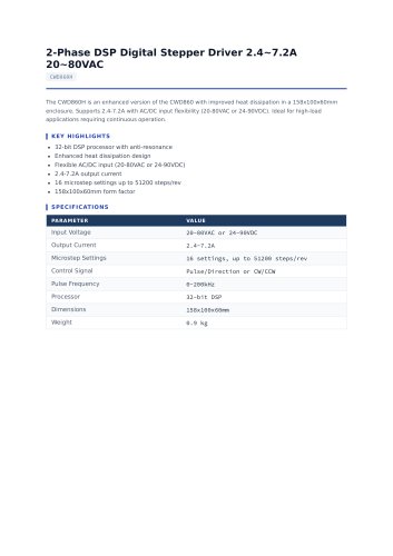 CWD860H_datasheet.pdf
2 Pages
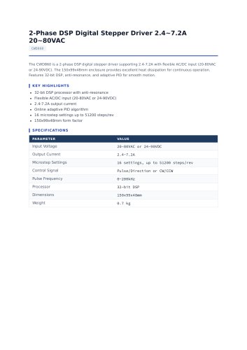 CWD860_datasheet.pdf
2 Pages
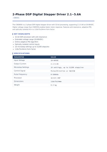 CWD856_datasheet.pdf
2 Pages
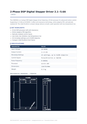 CWD556_datasheet.pdf
1 Page
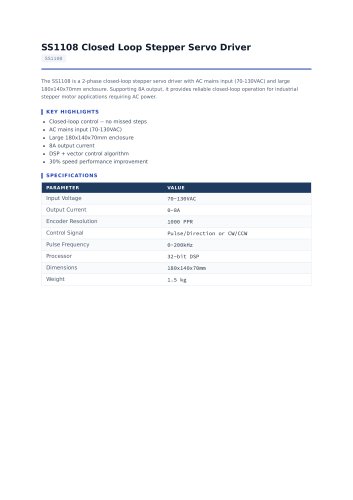 SS1108_datasheet.pdf
2 Pages
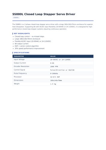 SS880L_datasheet.pdf
2 Pages
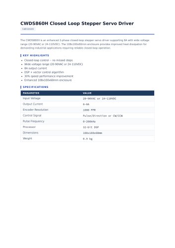 CWDS860H_datasheet.pdf
2 Pages
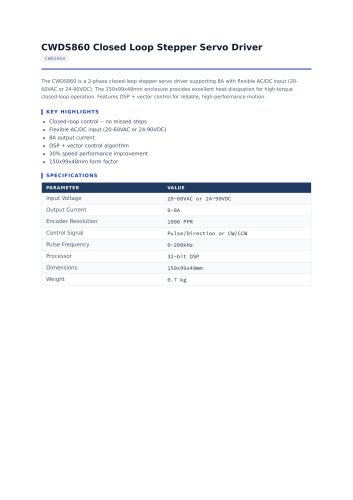 CWDS860_datasheet.pdf
2 Pages
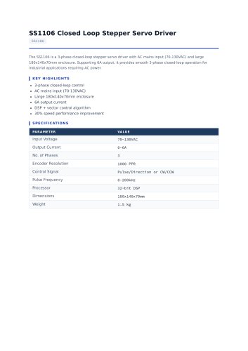 SS1106_datasheet.pdf
2 Pages
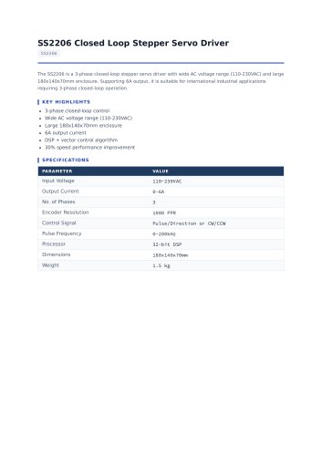 SS2206_datasheet.pdf
2 Pages
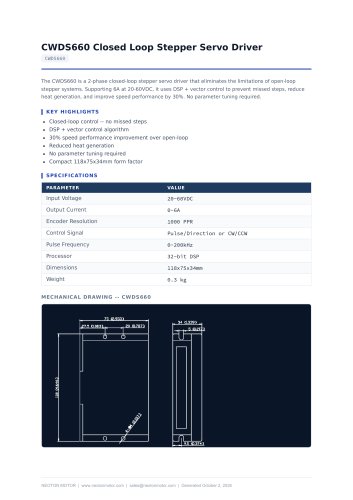 CWDS660_datasheet.pdf
1 Page
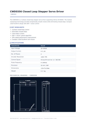 CWDS556_datasheet.pdf
1 Page
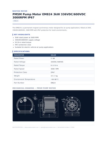 EM824_datasheet.pdf
1 Page
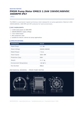 EM823_datasheet.pdf
1 Page
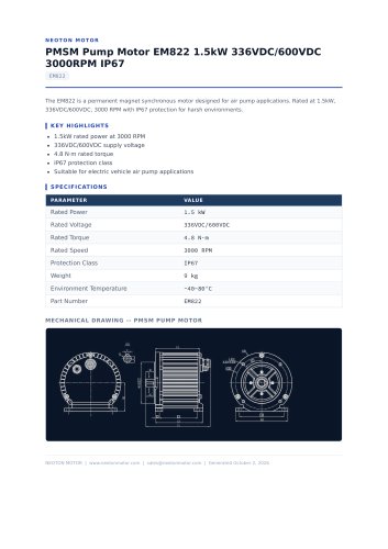 EM822_datasheet.pdf
1 Page
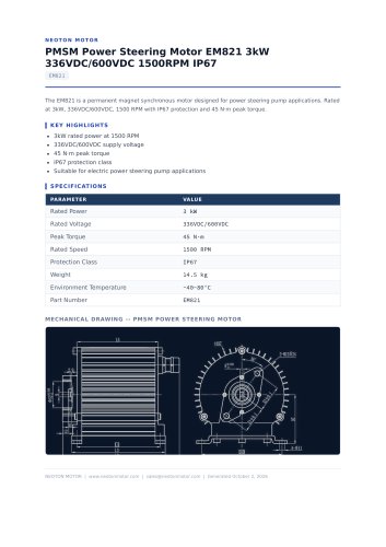 EM821_datasheet.pdf
1 Page
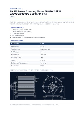 EM820_datasheet.pdf
1 Page
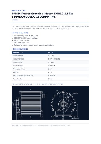 EM819_datasheet.pdf
1 Page
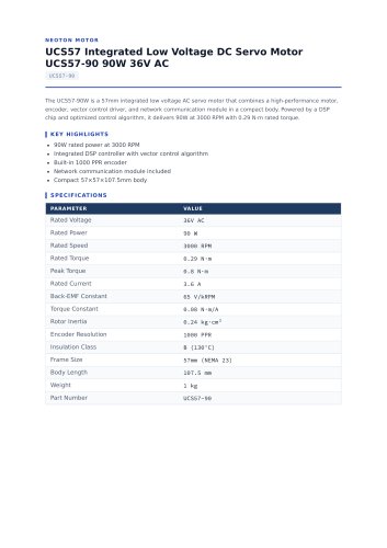 UCS57-90_datasheet.pdf
2 Pages
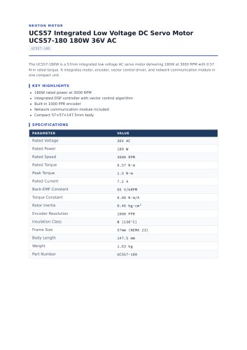 UCS57-180_datasheet.pdf
2 Pages
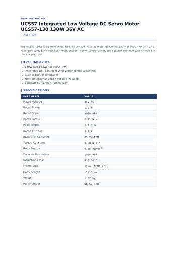 UCS57-130_datasheet.pdf
2 Pages
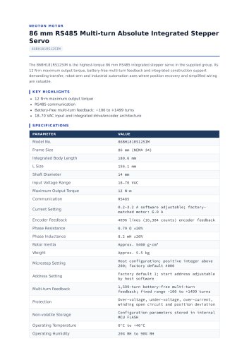 86BH181RS125IM_datasheet.pdf
2 Pages
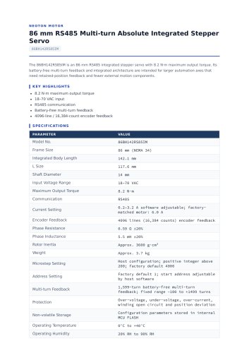 86BH142RS85IM_datasheet.pdf
2 Pages
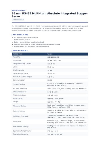 86BH122RS65IM_datasheet.pdf
2 Pages
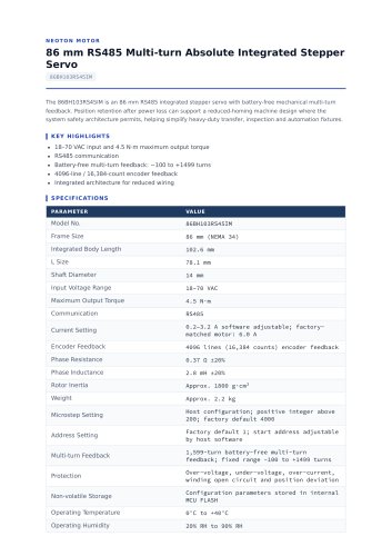 86BH103RS45IM_datasheet.pdf
2 Pages
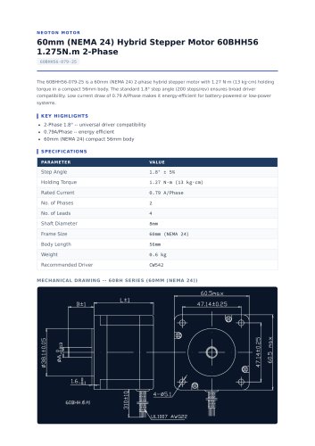 60BHH56-079-25_datasheet.pdf
2 Pages
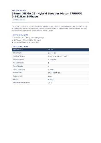 57BHP51-100-21_datasheet.pdf
4 Pages
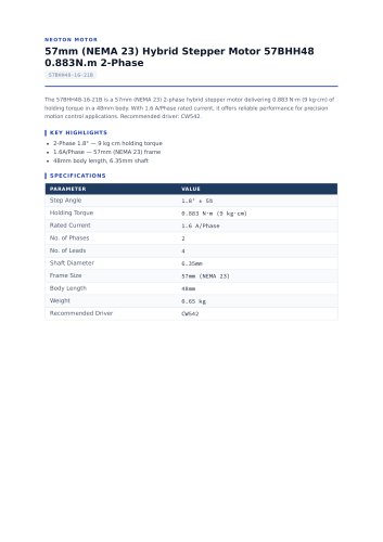 57BHH48-16-21B_datasheet.pdf
4 Pages
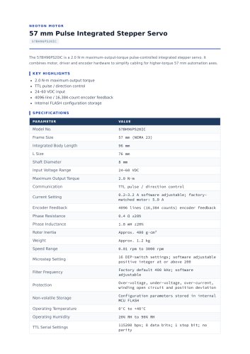 57BH96PS20IC_datasheet.pdf
2 Pages
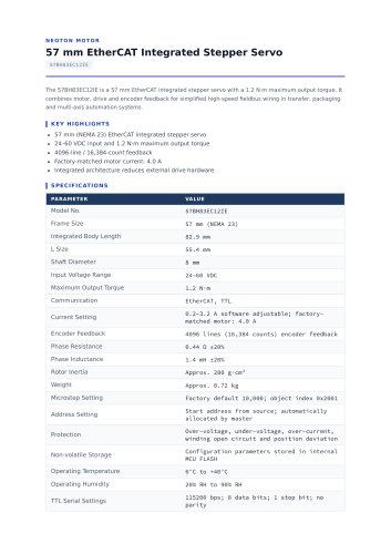 57BH83EC12IE_datasheet.pdf
2 Pages
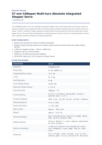 57BH80CA12IM_datasheet.pdf
2 Pages
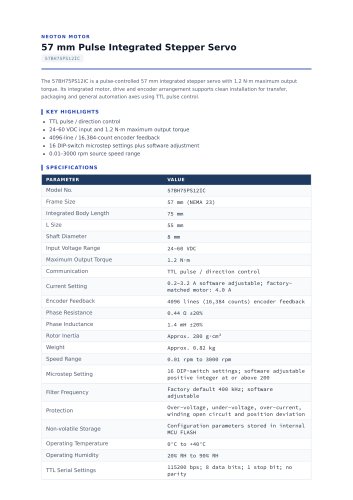 57BH75PS12IC_datasheet.pdf
2 Pages
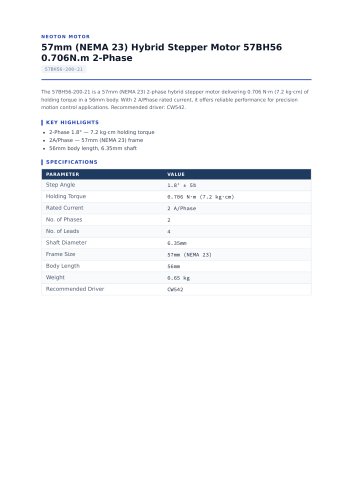 57BH56-200-21_datasheet.pdf
4 Pages
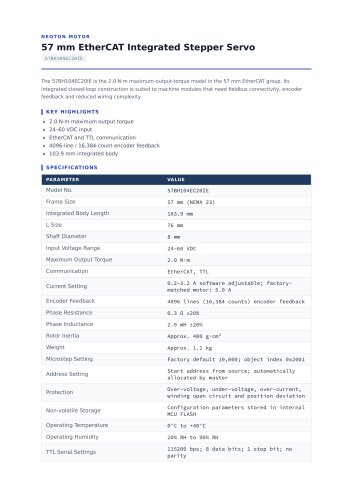 57BH104EC20IE_datasheet.pdf
2 Pages
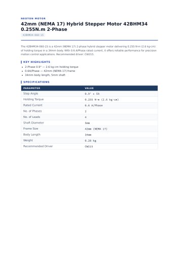 42BHM34-060-15_datasheet.pdf
4 Pages
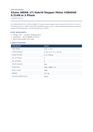 42BHH48-08A-24_datasheet.pdf
4 Pages
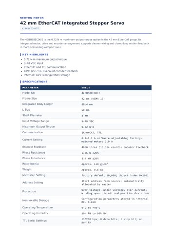 42BH88EC06IE_datasheet.pdf
2 Pages
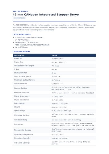 42BH79CA06IC_datasheet.pdf
2 Pages
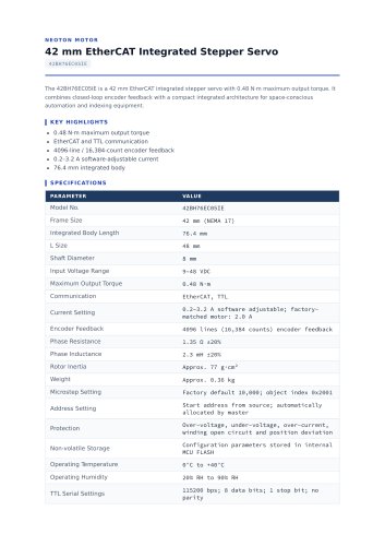 42BH76EC05IE_datasheet.pdf
2 Pages
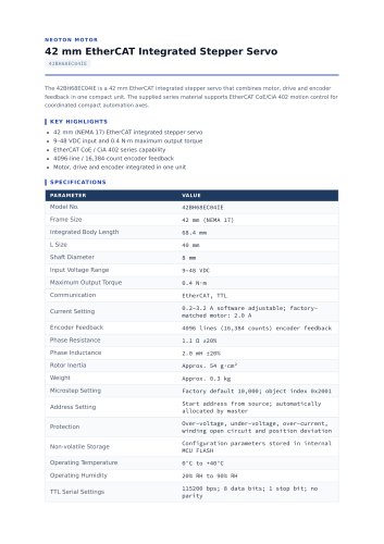 42BH68EC04IE_datasheet.pdf
2 Pages
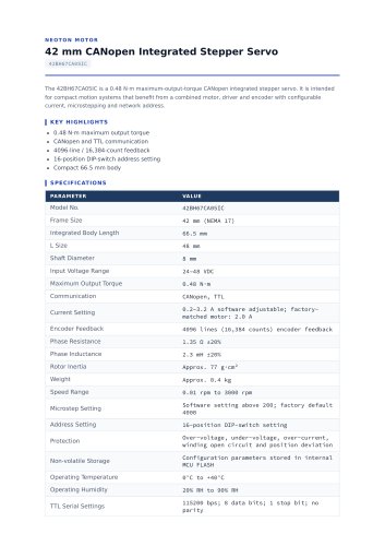 42BH67CA05IC_datasheet.pdf
2 Pages
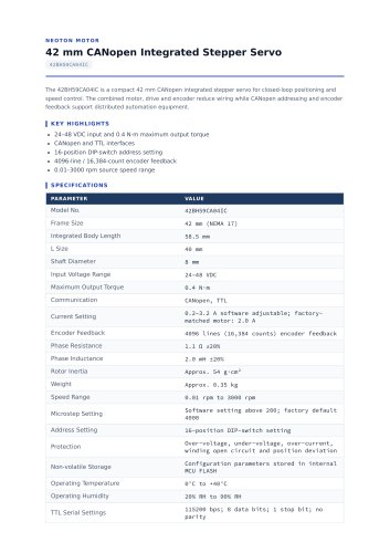 42BH59CA04IC_datasheet.pdf
2 Pages
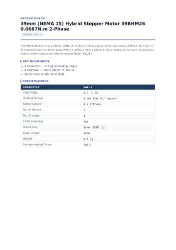 39BHM26-02A-17_datasheet.pdf
3 Pages
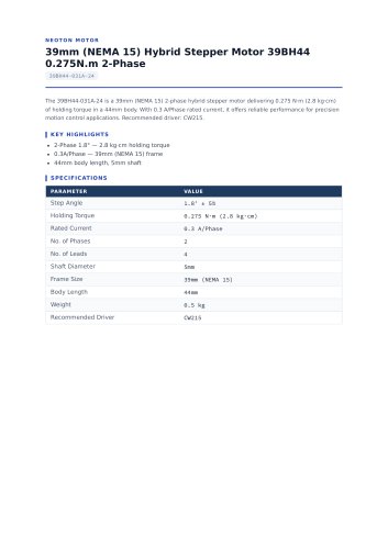 39BH44-031A-24_datasheet.pdf
3 Pages
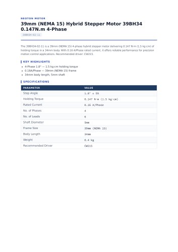 39BH34-02-11_datasheet.pdf
3 Pages
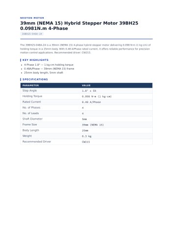 39BH25-048A-24_datasheet.pdf
3 Pages
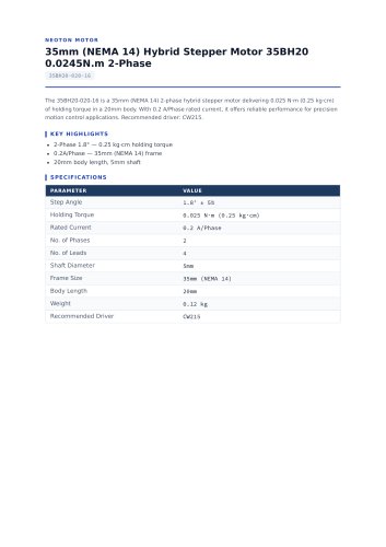 35BH20-020-16_datasheet.pdf
3 Pages
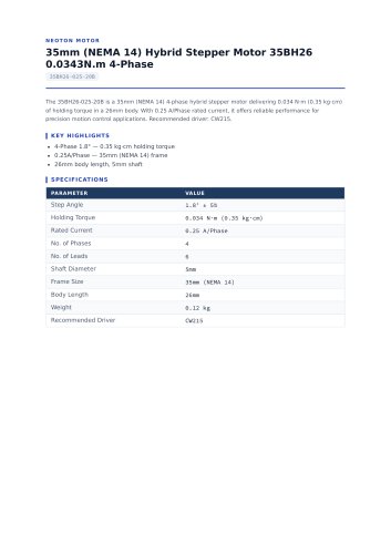 35BH26-025-20B_datasheet.pdf
3 Pages
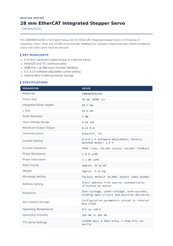 28BH86EC024IE_datasheet.pdf
2 Pages
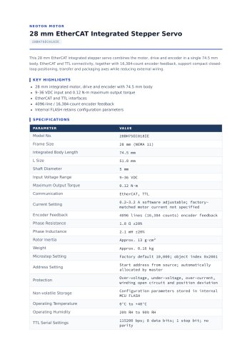 28BH75EC018IE_datasheet.pdf
2 Pages
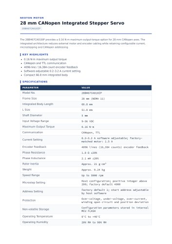 28BH67CA018IP_datasheet.pdf
2 Pages
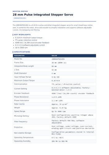 28BH66PS018IG_datasheet.pdf
2 Pages
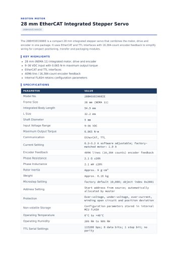 28BH55EC008IE_datasheet.pdf
2 Pages
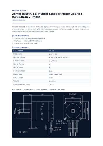 28BH51-100B-20_datasheet.pdf
2 Pages
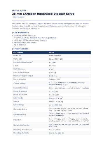 28BH47CA008IP_datasheet.pdf
2 Pages
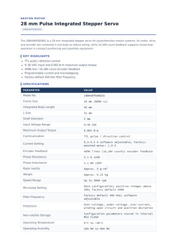 28BH46PS008IG_datasheet.pdf
2 Pages
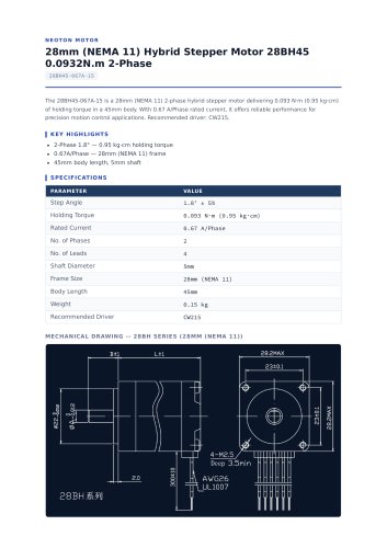 28BH45-067A-15_datasheet.pdf
2 Pages
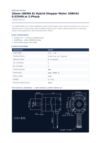 20BH42-080A-15_datasheet.pdf
2 Pages
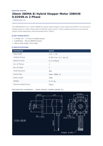 20BH38-061A-10_datasheet.pdf
2 Pages
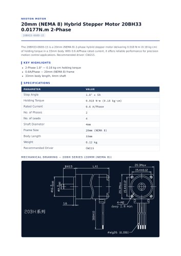 20BH33-060D-15_datasheet.pdf
2 Pages
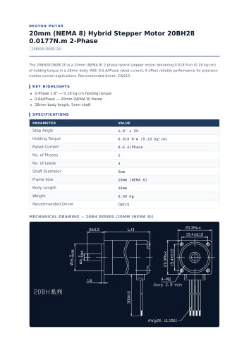 20BH28-060B-20_datasheet.pdf
2 Pages
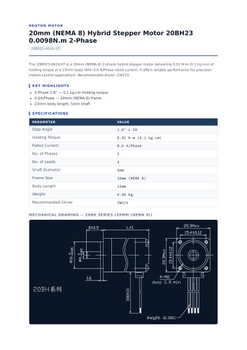 20BH23-061K-07_datasheet.pdf
2 Pages
- Electromotor
- DC electromotor
- Synchronous motor
- Alternating current motor
- Multipole motor
- EC motor
- Electromotor for industrial applications
- Three-phase motor
- 24 V motor
- Servo-motor
- 4-pole motor
- Compact electromotor
- High-efficiency electromotor
- 12 V motor
- Servo-amplifier
- Pump motor
- Stepper motor
- Permanent magnet motor
- High-performance servo motor
- AC servo-motor