Instruction manual and data sheet Torque Sensor Series 5000
1 /15Pages

Instruction manual and data sheet Torque Sensor Series 5000
1 /15Pages
Catalog excerpts
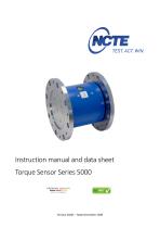
Instruction manual and data sheet Torque Sensor Series 5000 PREMIUM QUALITY Version 20/01 - State December 2020
Open the catalog to page 1
Copyright © NCTE AG® Torque Sensor Series 5000 Instruction Manual and Data Sheet. This instruction manual is property of NCTE AG®, D-82041 Oberhaching Unauthorized duplication, even in part, is not permitted. State: December 2020
Open the catalog to page 2
Instruction manual
Open the catalog to page 3
Dear customers, Thank you for your decision to buy our sensor products. You have chosen a high quality and extremely precise torque measuring system. This manual contains all the information necessary for you and the installation, operating and maintenance personnel to use your measuring system under the intended conditions of use. It contains important information to ensure proper and safe installation and operation. For these reasons, the Instruction manual must always be available at the place of use of the torque measuring system and always ready to hand. We reserve the right to make changes...
Open the catalog to page 5
Please note the enclosed sheet on the warning notes. 2.1 Intended use The sensors of the Series 5000 are designed exclusively for measuring torque and/or speed. The respective load range can be taken from the data sheet and must not be exceeded. Proper use also includes compliance with the commissioning, assembly, operating, ambient and maintenance conditions specified by the manufacturer. Any use beyond these is considered improper. The manufacturer is not liable for any damage resulting from such use. 2.2 Recalibration and duration of use A factory recalibration should be executed annually....
Open the catalog to page 6
Torque Sensor Series 5000 The 5000 series has been specially developed for measurements with high torque. The range extends up to torques > 10000 Nm. 3.1 Short description This series is mainly used in high performance test systems for motor vehicles, in rail applications, for stress testing of components and for process control of heavy loads or container handling. Other applications are professional test constructions and quality control in general. The transmitted torque can be measured statically and dynamically in real-time. Each sensor can be individually configured with many extras, e.g....
Open the catalog to page 7
3.5 Starting up After mounting the sensor, the following must be observed: Switch on power supply and check voltage value. (Voltage peaks at the sensor must be avoided, devices must be checked accordingly before connection to the sensor) Connect the sensor to the power supply. (using the cable supplied) Record the output signal of the sensor with high resistance. (A/D converter, oscilloscope, PC) Record output signal in mechanically unloaded state of the sensor. 3.6 Operation during regular mode Optimal measuring values are achieved when the sensor is used while maintaining the specific nominal...
Open the catalog to page 8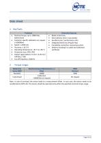
Note: In case of overload, the sensor leads to a measurement offset. In such case, the sensor needs to be recalibrated at NCTE AG. The sensor should be operated only within the specified nominal torque range.
Open the catalog to page 9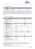
1 Specified values only apply to direct axial force on the shaft. If the axial force acts on the circlip, only 50 % of the force is permissible. 2 The accuracy class means that the linearity deviation as well as the circulation modulation, individually, are each less than or equal to the value specified as the accuracy class. The accuracy class must not be confused with a classification according to DIN 51309 or EA-10/14. 3 % ME: Related to the measuring range. 4 Zero point can be set to 5 V using a tare button. 5 The exact sensor-specific values can be found in the calibration certificate supplied....
Open the catalog to page 10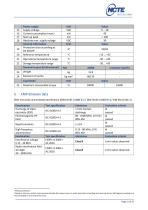
7 Based on the non-contact measurement principle the torque sensor is quite insensitive to bending and shearing forces. Self-aligning couplings are recommended in case of dynamic loads.
Open the catalog to page 11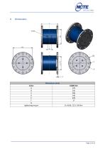
Dimensions [mm] Value A B C D E F G tightening torque
Open the catalog to page 12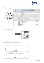
7 Wiring diagram Power supply and outputs 8 Sensor wiring 9 Speed sensor Magnetic (Hall effect) speed sensor with 60 CPR.
Open the catalog to page 13
You can obtain further or additional accessories and special requests in a personal discussion with your contact person for series products by calling +49 (0)89 66 56 19 30 or by e-mail: [email protected].
Open the catalog to page 14
Your experts for magnetostrictive sensors
Open the catalog to page 15All NCTE AG catalogs and technical brochures

- Dynamic torque sensor
- Rotary torque sensor
- Static torque sensor
- Analog torque sensor
- DC torque sensor
- Digital torque sensor
- Compact torque sensor
- USB torque sensor
- IP50 torque sensor
- Bidirectional torque sensor
- Torque sensor for the automobile industry
- IP65 torque sensor
- 5VDC torque sensor
- 6VDC torque sensor
- CAN Bus torque sensor
- 9VDC torque sensor
- CAN torque sensor