Instruction manual and data sheet Torque Sensor Series 2000
1 /18Pages
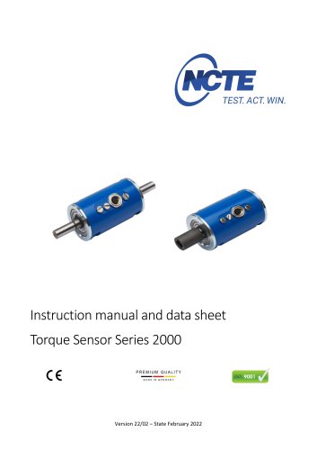
Instruction manual and data sheet Torque Sensor Series 2000
1 /18Pages
Catalog excerpts
Instruction manual and data sheet Torque Sensor Series 2000 PREMIUM QUALITY Version 22/02 - State February 2022
Open the catalog to page 1
Copyright © NCTE AG® Torque Sensor Series 2000 Instruction Manual and Data Sheet. This instruction manual is property of NCTE AG®, D-82041 Oberhaching Unauthorized duplication, even in part, is not permitted. State: February 2022
Open the catalog to page 2
Instruction manual
Open the catalog to page 3
Dear customers, Thank you for your decision to buy our sensor products. You have chosen a high quality and extremely precise torque measuring system. This manual contains all the information necessary for you and the installation, operating and maintenance personnel to use your measuring system under the intended conditions of use. It contains important information to ensure proper and safe installation and operation. For these reasons, the Instruction manual must always be available at the place of use of the torque measuring system and always ready to hand. We reserve the right to make changes...
Open the catalog to page 5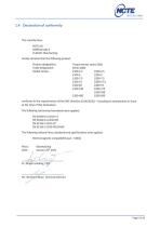
1.4 Declaration of conformity The manufacturer hereby declares that the following product Product designation: Torque sensor series 2000 Trade designation: Model names: conforms to the requirements of the EMC Directive 2014/30/EU - including its amendments in force at the time of this declaration. The following harmonized standards were applied: The following national laws, standards and specifications were applied: Electromagnetic compatibility law - EMCG Mr. Bernhard Mayr, Technical Director
Open the catalog to page 6
Please note the enclosed sheet on the warning notes. 2.1 Intended use The sensors of the series 2000 are designed exclusively for measuring torque and/or speed. The respective load range can be taken from the data sheet and must not be exceeded. Proper use also includes compliance with the commissioning, assembly, operating, ambient and maintenance conditions specified by the manufacturer. Any use beyond these is considered improper. The manufacturer is not liable for any damage resulting from such use. 2.2 Recalibration and duration of use A factory recalibration should be executed annually....
Open the catalog to page 7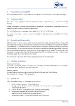
Torque Sensor Series 2000 The Series 2000 provides the easiest and most cost-effective entry into torque measurement technology. 3.1 Short description The series is mainly used in test stands, automation processes, production lines e.g. end-of-line tests and teaching. Torque measurement is possible both statically and dynamically. The mechanical connection is made via a square shaft (series 2100) or round shaft (series 2200). The Series 2000 provides an analogue output signal with +/-10 V, +/-5 V, 0-10 V or 0-5 V. The sensor is delivered as a ready-to-connect unit including 5m cable, keystones...
Open the catalog to page 8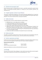
3.5 Operation during regular mode Optimal measuring values are achieved when the sensor is used while maintaining the specific nominal torque. If the permissible operating conditions are observed, the sensor operates trouble-free and maintenance-free. 3.6 Irregular operation, actions in case of failures If the sensor is mechanically overloaded (e.g. if the maximum permissible longitudinal force or torque limit is exceeded or if there are strong vibrations), the sensor may be damaged and the signal output may be distorted. In this case do not open the device. Contact NCTE AG directly. 3.7 Safety...
Open the catalog to page 9
3.11 Disposal The device must be returned to NCTE AG, Raiffeisenallee 3, D-82041 Oberhaching for disposal.
Open the catalog to page 10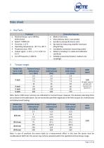
Note: In case of overload, the sensor leads to a measurement offset. In this case the sensor must be recalibrated at NCTE AG. The sensor may only be operated within the specified nominal torque range.
Open the catalog to page 11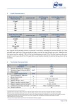
1 Specified values only apply to direct axial force on the shaft. If the axial force acts on the circlip, only 50 % of the force is permissible. 2 Specified values only apply to direct axial force on the shaft. If the axial force acts on the circlip, only 50 % of the force is permissible. 3The accuracy class means that the linearity deviation as well as the circulation modulation, individually, are each less than or equal to the value specified as the accuracy class. The accuracy class must not be confused with a classification according to DIN 51309 or EA-10/14. 4 %ME: Related to the measuring...
Open the catalog to page 12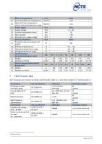
Effect of temperature Unit Zero point drift over temperature %/10 K Signal drift over temperature %/10 K within nominal temperature range Power supply Unit Supply voltage VDC Current consumption (max.) mA Start-up peak mA Absolute max. supply voltage VDC General information Unit Protection class according to EN IP 605296 Reference temperature °C Operation temperature range °C Storage temperature range °C Nominal torque Nm (bi-directional) Square shaft Weight g Moment of inertia g mm2 Nominal torque (bidirectional) Nm Round shaft Weight g Moment of inertia g mm2 EMV immunity and emitted interference...
Open the catalog to page 13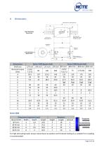
For high alternating loads, torque transmission by positive and frictional locking via a suitable fit or coupling is recommended.
Open the catalog to page 14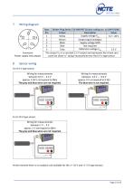
Wiring diagram Connector Power supply and outputs Type: Binder Plug Series 712-M9 IP67 (Colour coding acc. to DIN 47100) Pin Colour Description Value Supply voltage VCC 1 White 6 V – 28 V 2 Brown Output signal analogue 3 Black Supply voltage GND 4 Blue Not required Reference voltage Vref 5 Grey 2.5 V The output Vref is a constant 2.5 V output and represents the virtual zero point for direct +/- torque measurement for the 0-5 V type sensor. Sensor wiring For 0-5 V type sensor: Wiring for measurements between 0.5 V … 4.5 V approx. 2.50 V correspond to 0Nm The grey and blue wires are not required....
Open the catalog to page 15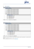
Order options Series 2100 (Square shaft) Measuring range [Nm] 2.5 including 5m cable and calibration certificate 5 including 5m cable and calibration certificate 7.5 including 5m cable and calibration certificate 15 including 5m cable and calibration certificate 60 including 5m cable and calibration certificate 140 including 5m cable and calibration certificate 400 including 5m cable and calibration certificate Output signal analog A1 Voltage output +/-10 V A2 Voltage output +/-5 V A3 Voltage output 0-10 V A4 Voltage output 0-5 V 2100 Example sensor configuration Series 2200 (Round shaft) Measuring...
Open the catalog to page 16All NCTE AG catalogs and technical brochures

- Dynamic torque sensor
- Rotary torque sensor
- Static torque sensor
- Analog torque sensor
- DC torque sensor
- Digital torque sensor
- Compact torque sensor
- USB torque sensor
- IP50 torque sensor
- Bidirectional torque sensor
- Torque sensor for the automobile industry
- IP65 torque sensor
- 5VDC torque sensor
- 6VDC torque sensor
- CAN Bus torque sensor
- 9VDC torque sensor
- CAN torque sensor