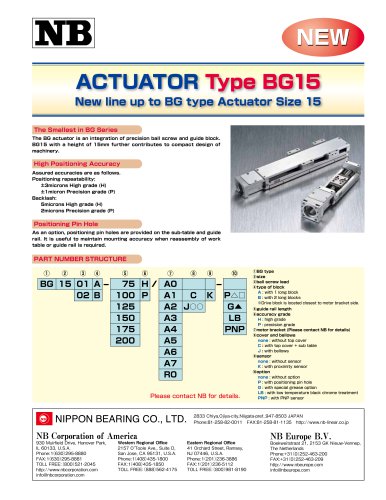
Catalog excerpts
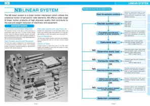
LINEAR SYSTEM LINEAR SYSTEM PROCESS FOR SELECTING NB LINEAR SYSTEM Check the application conditions The NB linear system is a linear motion mechanism which utilizes the rotational motion of ball and/or roller elements. NB offers a wide range of linear motion products of high precision quality that contribute to the size and weight reduction of machinery and equipment. Decide system type ADVANTAGES Low Friction and Excellent Response Despite the compactness of the NB linear system, the system uses relatively large rolling elements on a long raceway resulting in a high load capacity and a long travel life. Slide Guide Ball Spline Slide Bush Slide Way High Load Capacity and Long Travel Life The dynamic friction of the ball or roller elements is substantially lower than that of full-face surface sliding friction. Since the difference between dynamic and static frictional resistance is small, motion response is excellent in terms of positioning accuracy and in high speed applications with acceleration and deceleration. I dentify machine type to be u s e d , a p plic atio n c o n ditio n s , environmental conditions, and desired accuracy. High Precision and Smooth Movement The NB linear system is designed for the rolling elements to achieve extremely smooth motion. The raceway surface is finished by precision grinding for high precision movement with optimal clearance. Pre-select the size and number of linear systems Ease of Installation The NB linear system shortens machining and assembly time compared with that of a full-face surface sliding bearing. Calculate load Variety of Types A wide variety of types and sizes of the NB linear systems are available to best serve the purpose for every application and requirement. Determine static load OK Compute rated life OK Determine preload and accuracy OK Select lubrication and dust prevention method Confirm the space needed in the equipment Pre-select the size and number based on balance of machinery and other equipment as well as past experience. Calculate load on each system. Calculate average variable load. (refer to page Eng-6-8) Determine basic static load rating and allowable static moment by applying static safety factor. (refer to page Eng-3) Compute rated life and compare to required life. (refer to page Eng-4) D e cid e p reloa d a n d accu racy based on the operating conditions. (refer to each product description for preload and accuracy) Select lubrication and dust prevention method. (seals, bellows, covers) Confirm space and installation dimensions in consideration of the machine size and ease of maintenance.
Open the catalog to page 1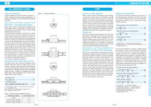
LINEAR SYSTEM ALLOWABLE LOAD Figure 1-1 Load and Moment A load is applied to the linear system as Figure 1-1 shows. Sometimes moment loads are applied to, for example, slide guides. Load and moment are defined as follows. Basic Static Load Rating (compliant with ISO14728-21) and Allowable Static Moment When excess load or impact load is applied to the linear system while it is stationary or moving slowly, a permanent deformation occurs on the rolling elements and the race way. If this deformation exceeds a certain limit, it causes vibration and noise during operation resulting in a...
Open the catalog to page 2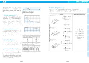
LINEAR SYSTEM ・ 3 10 Lh 2・ L ・n1・60 …………………… 9 ℓS L h: life time hr ℓ : stroke length S m cpm n1: number of cycles per minute In the linear system, the guide rail or shaft works as race way of the rolling elements. Therefore, the hardness of the rail or shaft is an important factor in determining the rated load. The rated load decreases as the hardness decrease below 58HRC. NB products hold appropriate hardness by advanced heat treatment technology. In case of using the rail or shaft of insufficient hardness, please take the hardness coefficient (Figure 1-2) into the life calculation...
Open the catalog to page 3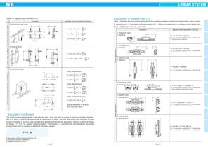
LINEAR SYSTEM Calculation of Applied Load 2 Table 1-5 Applied Load Calculation (2) applied load calculation formula 2 horizontal, side axes Table 1-6 shows the formulas for determining the applied load when moment is applied to the linear system. W: applied load (N) P: load applied to the linear system (N) ℓ: distance to applied load or to working center of gravity (mm) Table 1-6 Applied Load Calculation 3 condition applied load calculation formula 1 horizontal axis, 1 bearing Ep1: Mp equivalent coefficient with 1 bearing used Er: Mr equivalent coefficient Ey1: My equivalent coefficient...
Open the catalog to page 4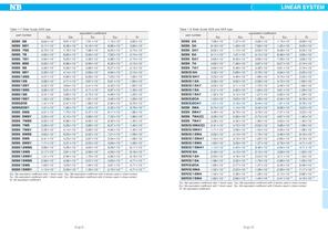
LINEAR SYSTEM Table 1-7 Slide Guide SEB type Table 1-8 Slide Guide SEB and SER type part number SEBS 7BY SEBS 9BS SEBS 9B Ep1: Mp equivalent coefficient with 1 block used Ep2: Mp equivalent coefficient with 2 blocks used in close contact Ey1: My equivalent coefficient with 1 block used Ey 2: My equivalent coefficient with 2 blocks used in close contact Er: Mr equivalent coefficient part number Ep1: Mp equivalent coefficient with 1 block used Ep2: Mp equivalent coefficient with 2 blocks used in close contact Ey1: My equivalent coefficient with 1 block used Ey 2: My equivalent coefficient...
Open the catalog to page 5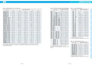
LINEAR SYSTEM Table 1-9 Slide Guide SGL, GL, and SGW type Table 1-10 Ball Spline・Rotary Ball Spline・Stroke Ball Spline equivalent coefficient part number E1 E2 part number Ep1: Mp equivalent coefficient with 1 block used Ep2: Mp equivalent coefficient with 2 blocks used in close contact Ey1: My equivalent coefficient with 1 block used Ey 2: My equivalent coefficient with 2 blocks used in close contact Er: Mr equivalent coefficient Table 1-11 Slide Bush SM type equivalent coefficient part number E1 E2 E1: equivalent coefficient with 1 bush used E 2 : equivalent coefficient with 2 bushes used...
Open the catalog to page 6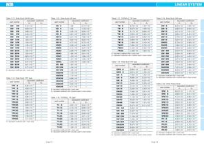
LINEAR SYSTEM Table 1-13 Slide Bush SM-W type equivalent coefficient part number E1 E2 3W Table 1-15 Slide Bush KB type equivalent coefficient part number E1 E2 E1: equivalent coefficient with 1 bush used E 2 : equivalent coefficient with 2 bushes used in close contact E1: equivalent coefficient with 1 bush used E1: equivalent coefficient with 1 bush used E 2 : equivalent coefficient with 2 bushes used in close contact Table 1-20 Slide Rotary Bush equivalent coefficient part number E1 E2 E1: equivalent coefficient with 1 bush used E 2: equivalent coefficient with 2 bushes used in close...
Open the catalog to page 7All NB catalogs and technical brochures
-
SLIDE SHAFT SPINDLE SHAFT
24 Pages
-
STROKE BUSH SLIDE ROTARY BUSH
14 Pages
-
TOPBALLR
13 Pages
-
SLIDE BUSH
74 Pages
-
SLIDE GUIDE
40 Pages
-
FIT Series
2 Pages
-
Actuator BG15
2 Pages
-
Linear System General Catalog
293 Pages
-
Slide Guide SEBS-BS
4 Pages
-
ROTARY BALL SPLINE SPB type
4 Pages
-
TOPBALL Slide Products
28 Pages
-
Compact Slide Way NYT/NYTS
2 Pages
-
BALL SPLINE SSP-AM type
2 Pages
-
SLIDE SCREW
4 Pages
-
ACTUATOR
39 Pages
Archived catalogs
-
General Catalog
289 Pages
-
NB - Slide Way
14 Pages
-
NB - Rotary Ball Spline
2 Pages
-
NB - Actuator
55 Pages
-
NB - Slide Bush
4 Pages
-
NB - Slide Rotary Series
14 Pages
-
NB - Miniature Slide Table
6 Pages
-
NB - Gonio way
8 Pages
-
NB - Slide guide
18 Pages
-
NB - Lienar system
23 Pages


