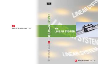
General Catalog
1 /289Pages

General Catalog
1 /289Pages
Catalog excerpts
2833 Chiya, Ojiya-city, Niigata-pref., 947-8503 JAPAN 930 Muirfield Drive, Hanover Park, IL60133 Western Regional Office 46750 Lakeview Blvd. Fremont, CA 94538 Eastern Regional Office 41 Orchard Street, Ramsey, NJ07446 Boekweitstraat 21, 21 53 GK Nieuw-Vennep, The Netherlands
Open the catalog to page 1
LINEAR SYSTEM
Open the catalog to page 2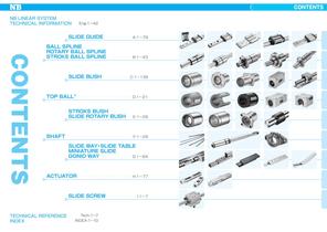
CONTENTS NB・LINEAR・SYSTEM TECHNICAL・INFORMATION・ Eng-1〜42 SLIDE GUIDE・ ・・・・・・・・・・・A-1〜79 CONTENTS CONTENTS BALL SPLINE ROTARY BALL SPLINE STROKE BALL SPLINE・ ・・・・・・・・・ B-1〜43 SLIDE BUSH・・・・・・・・・・・・C-1〜139 TOP BALL ・・・・・・・・・・・・・・・・・・・・・・ D-1〜21 R STROKE BUSH SLIDE ROTARY BUSH・ ・・ E-1〜29 SHAFT・ ・・・・・・・・・・・・・・・・・・・・・・・・・ F-1〜29 SLIDE WAY ・SLIDE TABLE MINIATURE SLIDE GONIO WAY・ ・・・・・・・・・・・・G-1〜64 ACTUATOR・・・・・・・・・・・・・・・・・・・・・・ H-1〜77 SLIDE SCREW・ ・・・・・・・・・・・ TECHNICAL・REFERENCE・ INDEX・ Tech-1〜7 INDEX-1〜10 I-1〜7
Open the catalog to page 3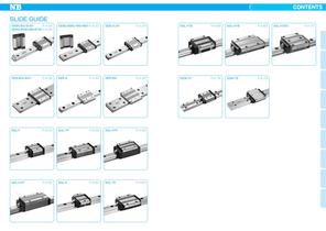
CONTENTS CONTENTS SLIDE GUIDE SEBS-BS/B/BY P.A-26 SEBS-BSM/BM/BYM P.A-26 SEBS-WBS/WB/WBY P.A-30 SEB-A/AY P.A-34 SGL-HTE P.A-66 SGL-HYE P.A-68 SEB-WA/WAY P.A-38 SER-A P.A-46 SER-WA P.A-48 SGW-TF P.A-76 SGW-TE P.A-78 SGL-F P.A-54 SGL-TF P.A-56 SGL-HTF P.A-58 SGL-HYF P.A-60 SGL-E P.A-62 SGL-TE P.A-64 SGL-HTEX P.A-70
Open the catalog to page 4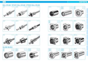
CONTENTS BALL SPLINEROTARY BALL SPLINESTROKE BALL SPLINE SSP P.B-18 SSPM P.B-20 SSPF P.B-22 SM-G-L P.C-20 SM-W KB-W SW-W P.C-22 P.C-74 P.C-94 SMF KBF SWF P.C-24 P.C-76 P.C-96 SSPT P.B-24 SSP-S P.B-26 SSP-C P.B-27 SMK KBK SWK P.C-26 P.C-78 P.C-98 SMT P.C-28 SMF-E P.C-30 SPR P.B-34 SPB P.B-36 SPLFS P.B-42 SMK-E P.C-32 SMT-E P.C-34 SMK-G-L P.C-36 SM-AJ KB-AJ SW-AJ P.C-16 P.C-70 P.C-90 SM-OP KB-OP SW-OP P.C-18 P.C-72 P.C-92 SMF-W KBF-W SWF-W P.C- 38 P.C- 80 P.C-100 SMT-W P.C-42 SLIDE BUSH SM KB SW P.C-14 P.C-68 P.C-88 SMK-W KBK-W SWK-W P.C- 40 P.C- 82 P.C-102
Open the catalog to page 5
CONTENTS SMFC KBFC P.C-44 P.C-84 SMKC KBKC P.C-46 P.C-86 SMTC P.C-48 GM GW P.C-104 P.C-106 GM-W P.C-105 SMA P.C-108 SMF-W-E P.C-50 SMK-W-E P.C-52 SMT-W-E P.C-54 SMA-W P.C-110 AK P.C-112 AK-W P.C-114 TRF P.C-56 TRK P.C-58 TRFC P.C-60 SMB P.C-116 SMP P.C-118 SMJ P.C-120 TRKC P.C-62 TRF-E P.C-64 TRK-E P.C-66 SME P.C-122 SME-W P.C-124 SMD P.C-126
Open the catalog to page 6
CONTENTS CE P.C-128 CD P.C-130 SWA P.C-132 TKE P.D-12 TKE-W P.D-13 TKD P.D-14 SWJ P.C-134 SWD P.C-136 RBW P.C-138 TKD-W P.D-15 TWA P.D-16 TWA-W P.D-17 TWJ P.D-18 TWJ-W P.D-19 TWD P.D-20 TWD-W P.D-21 TOPBALL R TK P.D-6 TK-OP TW-OP P.D-8 TKA P.D-6 P.D-10 TW TKA-W P.D-8 P.D-11
Open the catalog to page 7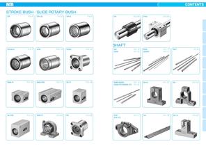
CONTENTS STROKE BUSHSLIDE ROTARY BUSH SR P.E-4 SR-UU P.E-5 SR-B P.E-6 FR P.E-28 FRA P.E-29 P.F- 6 P.F-10 SNS SNWS P.F- 7 P.F-11 SNT SHAFT SR-BUU P.E-7 SRE P.E-12 SREK P.E-14 SN SNW P.F-8 SMA-R P.E-16 SMA-RW P.E-17 AK-R P.E-18 SNB/SNSB P.F- 9 SNW-PD/SNWS-PD P.F-12 SH-A P.F-15 SH P.F-16 AK-RW P.E-19 SMP-R P.E-20 RK P.E-23 SHF SHF-FC SA P.F-18 WH-A P.F-20 P.F-17
Open the catalog to page 8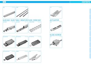
CONTENTS WA P.F-22 LWA P.F-23 RV SLIDE WAYSLIDE TABLEMINIATURE SLIDEGONIO WAY NV/NVS P.G-10 SV/SVS P.G-14 SVW/SVWS P.G-22 NVT/NVTS P.G-28 SVT/SVTS P.G-32 SYT/SYTS P.G-38 SYT-D/SYTS-D P.G-42 SYBS P.G-50 RVF P.G-60 P.G-62 ACTUATOR BG P.H-1 SLIDE SCREW SS P.I-7
Open the catalog to page 9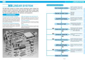
LINEAR SYSTEM LINEAR SYSTEM PROCESS FOR SELECTING NB LINEAR SYSTEM Check the application conditions The NB linear system is a linear motion mechanism which utilizes the rotational motion of ball and/or roller elements. NB offers a wide range of linear motion products of high precision quality that contribute to the size and weight reduction of machinery and equipment. Decide system type ADVANTAGES Low Friction and Excellent Response Despite the compactness of the NB linear system, the system uses relatively large rolling elements on a long raceway resulting in a high load capacity and a long...
Open the catalog to page 10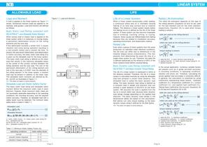
LINEAR SYSTEM ALLOWABLE LOAD LIFE Load and Moment Figure 1-1 Load and Moment A load is applied to the linear system as Figure 1-1 shows. Sometimes moment loads are applied to, for example, slide guides. Load and moment are defined as follows. Basic Static Load Rating (compliant with ISO14728-21) and Allowable Static Moment When excess load or impact load is applied to the linear system while it is stationary or moving slowly, a permanent deformation occurs on the rolling elements and the race way. If this deformation exceeds a certain limit, it causes vibration and noise during operation resulting...
Open the catalog to page 11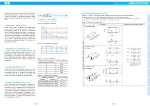
LINEAR SYSTEM ・ 3 10 Lh 2・ L ・n1・60 …………………… 9 ℓS L h: life time hr ℓ : stroke length S m cpm n1: number of cycles per minute In the linear system, the guide rail or shaft works as race way of the rolling elements. Therefore, the hardness of the rail or shaft is an important factor in determining the rated load. The rated load decreases as the hardness decrease below 58HRC. NB products hold appropriate hardness by advanced heat treatment technology. In case of using the rail or shaft of insufficient hardness, please take the hardness coefficient (Figure 1-2) into the life calculation equation....
Open the catalog to page 12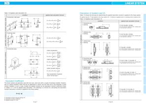
LINEAR SYSTEM Calculation of Applied Load 2 Table 1-5 Applied Load Calculation (2) applied load calculation formula 2 horizontal, side axes Table 1-6 shows the formulas for determining the applied load when moment is applied to the linear system. W: applied load (N) P: load applied to the linear system (N) ℓ: distance to applied load or to working center of gravity (mm) P1P 2P3P4 1 ℓ W 2Y Table 1-6 Applied Load Calculation 3 condition P 2SP4S applied load calculation formula 1 horizontal axis, 1 bearing 1 xo P1SP3S W W 4 2X PWEp1W 1ErW 2 ℓ ℓ 1 xo W− W 4 2X Ep1: Mp equivalent coefficient with...
Open the catalog to page 13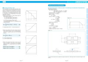
LINEAR SYSTEM RATED LIFE CALCULATION EXAMPLE 1 ●Average Applied Load 2 Horizontal Axes, 2 Blocks each, Considering Acceleration/Deceleration The load applied to a linear system generally varies with the travel distance depending on how the system is operated. This includes the start/stop processes of the reciprocating motion and work on the system. The average applied load is used to compute the life corresponding to the actual application conditions. ①When the load varies in a step manner with the travel distance (Figure 1-7). ℓ1 is the travel distance under load P1 ℓ2 is the travel distance...
Open the catalog to page 18All NB catalogs and technical brochures
 SLIDE SHAFT SPINDLE SHAFT
24 Pages
 STROKE BUSH SLIDE ROTARY BUSH
14 Pages
 TOPBALLR
13 Pages
 SLIDE BUSH
74 Pages
 SLIDE GUIDE
40 Pages
 FIT Series
2 Pages
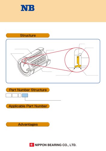
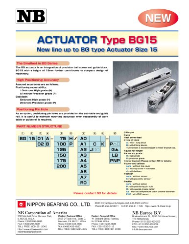 Actuator BG15
2 Pages
 Linear System General Catalog
293 Pages
 Slide Guide SEBS-BS
4 Pages
 ROTARY BALL SPLINE SPB type
4 Pages
 TOPBALL Slide Products
28 Pages
 Compact Slide Way NYT/NYTS
2 Pages
 BALL SPLINE SSP-AM type
2 Pages
 SLIDE SCREW
4 Pages
 ACTUATOR
39 Pages
 LINEAR SYSTEM
21 Pages


Archived catalogs
 NB - Slide Way
14 Pages
 NB - Rotary Ball Spline
2 Pages
 NB - Actuator
55 Pages
 NB - Slide Bush
4 Pages
 NB - Slide Rotary Series
14 Pages
 NB - Miniature Slide Table
6 Pages
 NB - Gonio way
8 Pages
 NB - Slide guide
18 Pages
 NB - Lienar system
23 Pages
- Linear actuator
- Electric actuator
- Compact actuator
- Screw actuator
- Linear motion system
- Precision actuator
- Ball screw actuator
- Positioning actuator
- Steel linear guide
- Ball bearing linear guide
- Ball screw
- Slide carriage block
- Compact linear guide
- High-speed actuator
- Precision linear guide
- Metal ball screw
- Metal shaft
- Machining spindle
- Track linear guide