Catalog excerpts

SLIDE SCREW SLIDE SCREW I-1
Open the catalog to page 1
SLIDE SCREW The NB slide screw converts rotational motion into linear motion by utilizing the friction between radial ball bearings and a shaft. This simple mechanism eases maintenance and installation work. The slide screw is most commonly used as transport devices in many types of machines, and is not intended for accurate positioning The NB slide screw consists of two aluminum blocks, each with three radial bearings with a fixed angle between them. A round shaft is inserted between the two blocks, and its rotation produces linear motion determined by the contact angle between the shaft...
Open the catalog to page 2
Allowable Rotational Speed When the rotational speed is increased and approaches the shaft resonant frequency, the shaft is disabled from further operation. This speed is called the critical speed and can be obtained by the following equation. In order to leave a sufficient safety margin, the maximum operating speed should be set at about 80% of the calculated value. Figure 1-3 Mounting of Slide Screw E: modulus of direct elasticity (N/mm2) A: installation coefficient (refer to Figure I-3) I: geometrical moment of inertia (mm4) A: cross-sectional area of the shaft (mm2) If modulus of direct...
Open the catalog to page 3
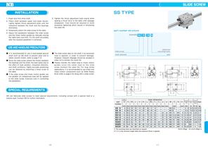
Clean dust from drive shaft. Place shaft between upper and lower blocks. Lightly tighten thrust adjustment bolts until the clearance between the shaft and the bearings Temporarily attach the slide screw to the table. Adjust the parallelism between the slide screw and the linear motion guides by manually moving the table back and forth. Fix the shaft accurately after the required parallelism is achieved. Tighten the thrust adjustment bolts evenly while appling a thrust force to the table untill slippage disappears. Care should be required to avoid excessive tightening which results in...
Open the catalog to page 4All NB Europe catalogs and technical brochures
-
Interchange table
28 Pages
-
FIT SERIES
2 Pages
-
Topball&Slide shaft products
28 Pages
-
Catalogue general
564 Pages
-
LINEAR SYSTEM
21 Pages
-
SLIDE ROTARY BUSH
4 Pages
-
Stainless Steel SGL Guide
2 Pages
-
SLIDE GUIDE
4 Pages
-
ACTUATOR Type BG15
2 Pages
-
ROTARY BALL SPLINE SPB type
4 Pages
-
NB REVERSE-SEAL
2 Pages
-
LEAFLET OF SHAFT DRAWINGS
9 Pages
-
ACTUATOR
39 Pages
-
SLIDE WAY
33 Pages
-
SHAFT
15 Pages
-
STROKE BUSH
15 Pages
-
TOPBALL
11 Pages
-
SLIDE BUSH
70 Pages
-
BALL SCREW SPLINE
4 Pages
-
BALL SPLINE
22 Pages
-
SLIDE GUIDE
40 Pages
-
General catalog
289 Pages
-
TECHNICAL REFERENCE
4 Pages
-
TOPBALL™ Slide Products
28 Pages
-
Rotary Ball Spline SPR Type
2 Pages
-
Slide Rotary Series
14 Pages
-
Gonio Way RVF Type
8 Pages
-
STUDROLLER™ NV/NVT Type
14 Pages
-
Slide Guide SGL-HYF and HYE
8 Pages
-
Slide Bush SM G-L/SMK G-L
2 Pages
-
Shaft Leaf
9 Pages
Archived catalogs
-
Linear Systems
8 Pages


