- Catalogs
- NATIONAL INSTRUMENTS
- Counter/Timer
Counter/Timer
1 /10Pages

Counter/Timer
1 /10Pages
Catalog excerpts
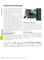
Data Acquisition and Signal Conditioning Counter/Timer Overview Counter/Timer Overview You can use the versatile National Instruments counter/timer devices to create a wide variety of measurement solutions, including measuring a number of time-related quantities, counting events or totalizing, and monitoring position with quadrature encoders. You can also use counter/timers to generate pulses and pulse trains. Counter/timers often fulfill critical timing functions as components of complex measurement systems. The NI 660x counter/timers use the NI-TIO, a National Instruments ASIC chip specifically designed to meet the counting and timing requirements of measurement applications that are beyond the capabilities of off-the-shelf components. The wider functionality and simple programming interface make the NI 660x your best choice for counting and timing applications. Example applications include frequency measurement, position measurement, generation of retriggerable pulses, frequency shiftkeying, two-signal edge separation measurements, continuous buffered event counting, and continuous buffered pulse train measurements. The NI 660x counter/timer devices are readily integrated into measurement systems that require synchronization across multiple hardware devices because they are equipped with the National Instruments PXI trigger bus or the RTSI bus. See the counter/timer tutorial on page 789 for more information. In addition to counter/timer functionality, the NI 660x products include TTL/CMOS-compatible digital I/O ports that are bit configurable for input or output. Counter/Timer Size or Number of Bits The counter size or number of bits indicates how high a counter can count. For example, a 32-bit counter can count up to 232-1 or 4,294,967,295 before it rolls over. A high number of bits is beneficial in cases such as pulse width measurements where a wide dynamic range is required. For example, if you measure pulse widths with a 12.5 ns resolution (80 MHz timebase) using a counter/timer with 32 bits, you can measure pulse widths up to 53 s [(232-1) x 12.5 ns)] with 12.5 ns resolution. Maximum Source Frequency Counter/Timer Considerations Number of Counter/Timers The counter/timer is a basic unit of hardware functionality on a measurement device. The more counter/timers there are on a device, the more counting/timing operations that device can simultaneously perform. The number of DMA channels determines how many buffered, high-speed operations can be simultaneously performed. See page 393 for more information. Size 32 bits 32 bits Compatibility 5 V TTL/CMOS 5 V TTL/CMOS Maximum source frequency represents the speed of the fastest signal the counter can count. If you use a higher source frequency, you can achieve higher resolution. For example, an 80 MHz counter can count pulses that are 12.5 ns (1⁄80 x 10 ) apart. You can use prescalers to increase the maximum source frequency for event counting and frequency measurement. 6 Debouncing/ Glitch Oscillator Removal Stability ✓ 50 ppm ✓ 50 ppm ✓ Source Frequency with prescalers is 60 MHz for the NI 6601 and 125 MHz for the NI 6602 and NI 6608. These frequencies are dependent on drive strength of input signal and cable length. Consider these speeds to be the maximum. 2DMA transfers have higher throughput than interrupt transfers. See page 393 for detailed specifications. National Instruments • Tel: (800) 433-3488 • Fax: (512) 683-9300 • [email protected]
Open the catalog to page 1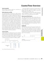
Counter/Timer Overview Signal compatibility indicates the signal levels a counter/timer can measure or output, such as TTL/CMOS. Timebase Stability Timebase stability can be important when you need to make highquality measurements. Crystal oscillators typically form the basis of electrical circuits used to drive timing of a measurement application. In an ideal case, the oscillation frequency would be constant, but in reality, many factors influence the the behavior of an oscillator. A commonly used measure of quality for an oscillator is stability. Start of Measurement Debouncing and Glitch Removal...
Open the catalog to page 2
32-Bit Counter/Timers NI 660x • Up to eight 32-bit counter/timers • 80 MHz maximum source frequency (125 MHz with prescalers) • Debouncing and glitch removal • High-stability timebase (PXI-6608 only) • GPS-based synchronization (PXI-6608 only) • NI DAQ driver simplifies configuration and measurements Operating Systems • Windows 2000/NT/XP • Real-time performance with LabVIEW (p. 134) • Others such as Linux and Mac OS X (page 187) Recommended Software • LabVIEW • LabWindows/CVI • Measurement Studio Other Compatible Software • Visual Basic • Visual C/C++, C# Driver Software (included) • NI-DAQ...
Open the catalog to page 3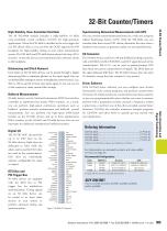
32-Bit Counter/Timers Synchronizing Networked Measurements with GPS The NI PXI-6608 module includes a high-stability 10 MHz oven-controlled crystal oscillator (OCXO) for high-precision applications. When the PXI-6608 is installed in the star trigger slot of a PXI chassis (Slot 2), you can drive the OCXO signal to the PXI backplane for high-stability timing of your entire measurement system. The PXI-6602 and PXI-6608 feature phase-lock loop (PLL) circuitry so that the devices can synchronize their reference clocks to the backplane. You can correlate measurements performed in a wide area using...
Open the catalog to page 4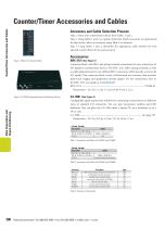
Counter/Timer Accessories and Cables Counter/Timer Accessories and Cables Accessory and Cable Selection Process Step 1. Select your counter/timer device from Tables 1 and 2. Step 2. Using Tables 1 and 2 as a guide, determine which accessories are appropriate for that device. Select an accessory using Table 3 as reference. Step 3. Using Tables 1 and 2, determine the appropriate cable solution for your selected counter/timer device and accessory. Accessories Figure 1. BNC-2121 Connector Block Data Acquisition and Signal Conditioning Table 1. Accessories and Cables for PXI-6601 and PCI-6602 Cables...
Open the catalog to page 5
Counter/Timer Accessories and Cables SCB-68 Shielded I/O Connector Block (See Figure 3) TBX-68 I/O Connector Block with DIN-Rail Mounting (See Figure 5) Figure 4. TB-2715 I/O Terminal Block Figure 5. TBX-68 I/O Connector Block Data Acquisition and Signal Conditioning Figure 6. CB-68LP and CB-68LPR I/O Connector Blocks National Instruments • Tel: (800) 433-3488 • Fax: (512) 683-9300 • [email protected]
Open the catalog to page 6All NATIONAL INSTRUMENTS catalogs and technical brochures
 NI 9381
10 Pages
 NI 9402
9 Pages
 NI PXIe-6612
12 Pages
 ds-392
7 Pages
 ETC_196
9 Pages
 ds-293
13 Pages
 ds-353
14 Pages
 ds-361
5 Pages
 NI WSN-3202
13 Pages
 cat_ni31xx
5 Pages
 PXI-4072 FlexDMM
5 Pages
 GPIB-USB-HS
7 Pages
 2005_6175_161_101
4 Pages
 Digital I/O,
9 Pages
 NI PCI-6624, NI PXI-6624
8 Pages
 NI PCIe-6321
15 Pages
 NI USB-6509
8 Pages
 NI_PCI-6713.
5 Pages
 NI_PCIe-6363
5 Pages
 NI_GPIB-USB-HS
4 Pages
 Counter_Timer_Devices
1 Page
 NI_EVS-1464
9 Pages
 daqsc208-209_212-2
2 Pages
 ds-153
18 Pages
 ds-37
ds-3714 Pages
 NI4065
6 Pages
 4daqsc253
17 Pages
 NI_1778_Smart_Camera
5 Pages
 NI_PCI-5122
5 Pages
 NI_EVS-1464_(Windows)
9 Pages
 4daqsc253-265_194-196
17 Pages
 NI-Datasheet-ds-293
13 Pages
 NI_PXIe-8100_RT
3 Pages
 NI_FPT-1015
3 Pages
 NI_PXI-2501
5 Pages
 2005_6174_161_101_d
5 Pages
 cat_FET
3 Pages
 cat_evs1464RT
9 Pages
 4daqsc253-265
17 Pages
 043918301101dlr
7 Pages
 4daqsc208-209
2 Pages
 usb-datasheet
14 Pages
 NI_9478
4 Pages
 NI_9472_Measurement_System
4 Pages
 NI_9402_Measurement_System
4 Pages
 NI_9263_Measurement_System
4 Pages


Archived catalogs
 NI_9203_Measurement_System
4 Pages
 NI_9208_Measurement_System
4 Pages
 NI_9239_Measurement_
4 Pages
 _Measurement_System
4 Pages
 Measurement_System
4 Pages
 _Measurement_
4 Pages
 NI_cDAQ-9171
3 Pages
 NI_cDAQ-9174
5 Pages
 NI_cDAQ-9178
5 Pages
 NI_cDAQ-9181
4 Pages
 NI_cDAQ-9188
5 Pages
 Wireless_Chassis
1 Page
 NI_cDAQ-9139
4 Pages
 BNC-2121
3 Pages
 PXI Embedded Controllers
1 Page
 LabVIEW Real-Time Module
3 Pages
 NI CompactDAQ Chassis
1 Page


- LCD screen
- Monitor with touchscreen
- Industrial monitor
- Management software solution
- Automation software solution
- VESA mounting monitor
- Analysis software solution
- Process software
- Panel-mount screen
- Windows software
- Real-time software
- Computer-aided design software
- Cloud-based software
- IO module
- Control software
- USB monitor
- Analog I/O
- Design software solution
- Digital IO module