

connectors DIN 43650

connectors DIN 43650
- TP10V36A1 Timer: Operates on 7 to 36VDC with a maximum intensity of 1A. Time settings range from 1 second to 99 hours, 59 minutes, and 59 seconds. It has an IP65 protection rating when mounted on a DIN43650A connector base.
- TP20V240A1 Timer: Supports 24 to 240 VDC/VAC (50-60Hz) with a maximum intensity of 1A. Time ON ranges from 0.5 to 10 seconds, and Time OFF from 0.5 to 45 minutes, operating in a cyclical ON-OFF mode.
- EES24V2/0.5A Power Saver: Accepts 5 to 27VDC power supply, with a maximum pull-in current of 2A and hold current of 0.5A. Offers voltage reduction to 50%, 33%, or 25% of nominal voltage.
- Timer Setting: The TP10V36A1 timer is configured using MODE, ADD, DEC, and RESET buttons to set opening and closing times and select operational modes (ON, OFF, ON-OFF, OFF-ON).
- Electrical Connection: Provides detailed steps for connecting electrical components using DIN43650-A connectors, including removing screws, connectors, and rubber pieces to access power terminals.
Catalog excerpts
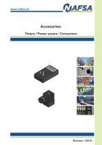
Accesories: Timers / Power savers / Connectors
Open the catalog to page 1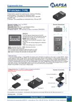
Programmable timer TP10V36A1 TYPE These timers control the opening and closing of feeding electromagnet. They have two operation ways: 1) Cyclical: Two possibilities at scheduled time, ON-OFF and OFF-ON. 2) Simple: Two possibilities at scheduled time, ON and OFF. Standard voltage: from 7 to 36VDC Maximum intensity: 1A Adjustable time: from 1 sec until 99h59min59sec Work temperature range: -10ºC to 50ºC Protection rate IP: IP65 mounted on base of connector DIN43650A General dimensions First two figures (beginning by the left) represent the hours, next two figures are the minutes and the last two...
Open the catalog to page 2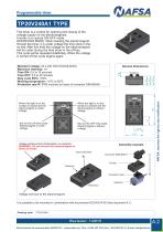
Programmable timer TP20V240A1 TYPE This timer is a control for opening and closing of the voltage supply on the electromagnets. It works in a cyclical ON-OFF mode. OPERATING MODE: When feeding the electromagnet through the timer, it is under voltage the time show in the on key. After this time the voltage on the electromagnet will be cutter during the time show in the off key. This cycle will be repeated indefinitely. When the voltage in turned off the cycle begins again. Standard voltage: 24 a 240 VDC/VAC(50-60Hz) Maximum intensity: 1A Time ON: 0,5 to 10 seconds Time OFF: 0,5 to 45 minutes Duty...
Open the catalog to page 3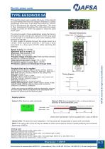
Electric power saver TYPE:EES24V2/0.5A This electric power saver supplies full power to the solenoid for a pre-defined time then the voltage is lowered to a certain percentage of the input. That value can be 50%Vn, 33%Vn, 25%Vn according to the selected configuration. This value is then maintained throughout the time until the supply voltage is turned off. When the system is reset the cycle starts again. General dimensions The circuit is used in those applications where the force in the beginning of the stroke of a solenoid of 100% duty cycle is not enough or in applications where less heating...
Open the catalog to page 4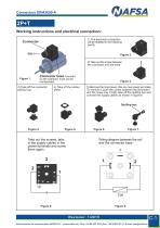
2P+T Working instructions and electrical connection: 1) The electrical connection will be detailed in the following points. Figure 2. 2) Take out the screw between the connector and the base. Connector base mounted on the solenoid, must not be manipulated. 3) Take off the connector pulling it up. 4) Take off the rubber piece. Figure 3. 5) Remove the inner piece, this one has power terminals. To remove it, push the carrier between the terminals 1 and the mass one. Finally take off the stuffing box and connect the supply cables as shown in figure 8. Take out the screws, take in the supply cables...
Open the catalog to page 5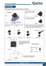
2P+T/C/2D Working instructions and electrical connection: 1) The electrical connection will be detailed in the following points. Figure 2. 2) Take out the screw between the connector and the base. Connector base mounted on the solenoid, must not be manipulated. 3) Take off the connector pulling it up. 4) Take off the rubber piece. Figure 3. 5) Remove the inner piece, this one has power terminals. To remove it, push the carrier between the terminals 1 and the mass one. Finally take off the stuffing box and connect the supply cables as shown in figure 8. 1 Take out the screws, take in the supply...
Open the catalog to page 6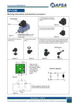
2P+T/2D Working instructions and electrical connection: 1) The electrical connection will be detailed in the following points. Figure 2. 2) Take out the screw between the connector and the base. Connector base mounted on the solenoid, must not be manipulated. 3) Take off the connector pulling it up. 4) Take off the rubber piece. Figure 3. 5) Remove the inner piece, this one has power terminals. To remove it, push the carrier between the terminals 1 and the mass one. Finally take off the stuffing box and connect the supply cables as shown in figure 8. 1 Take out the screws, take in the supply...
Open the catalog to page 7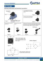
2P+T/C/4D Working instructions and electrical connection: 1) The electrical connection will be detailed in the following points. Figure 2. 2) Take out the screw between the connector and the base. Connector base mounted on the solenoid, must not be manipulated. 4) Take off the rubber piece. 3) Take off the connector pulling it up. Figure 3. 5) Remove the inner piece, this one has power terminals. To remove it, push the carrier between the terminals 1 and the mass one. Finally take off the stuffing box and connect the supply cables as shown in figure 8. Stuffing box Take out the screws, take in...
Open the catalog to page 8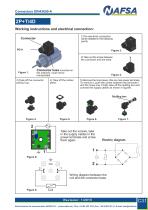
2P+T/4D Working instructions and electrical connection: 1)The electrical connection will be detailed in the following points. Figure 2. 2) Take out the screw between the connector and the base. Connector base mounted on the solenoid, must not be manipulated 3) Take off the connector pulling it up. 4) Take off the rubber piece. 5) Remove the inner piece, this one has power terminals. To remove it, push the carrier between the terminals 1 and the mass one. Finally take off the stuffing box and connect the supply cables as shown in figure8. 2 Take out the screws, take in the supply cables in the...
Open the catalog to page 9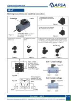
3P+T Working instructions and electrical connection: Connector 1)The electrical connection will be detailed in the following points. Figure 2. 2) Take out the screw between the connector and the base. Connector base mounted on the solenoid, must not be manipulated 3) Take off the connector pulling it up. 4) Take off the rubber piece. 5) Remove the inner piece, this one has power terminals. To remove it, push the carrier between the terminals 1 and the mass one. Finally take off the stuffing box and connect the supply cables as shown in figure 8. Stuffing box Take out the screws, take in the supply...
Open the catalog to page 10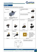
2P+T/G Working instructions and electrical connection: 1) The electrical connection will be detailed in the following points. Figure 2. 2) Take out the screw between the connector and the base. Connector base mounted on the solenoid, must not be manipulated 3) Take off the connector pulling it up. Figure 4. 7) Remove the electronic 4) Take off the rubber piece. 6) Remove the interior piece, which has the power terminals. 9) Conect the supply cables Take out the screws, take in the supply cables in the power terminals and screw them again. Wiring diagram between the coil and the connector base
Open the catalog to page 11All NAFSA catalogs and technical brochures
 CU20CP25-E
1 Page
 CU20CP100-E
1 Page
 CU20CPB
1 Page
 CU20CP25-30-24VDC-25%
1 Page
 CU20CP100-30-24VDC-100%
1 Page
 CU20CP25-2L
1 Page
 CU20CP100-2L
1 Page
 CP38
CP381 Page
 C30-M5-NC2
1 Page
 ERM300-35
1 Page
 VM135E
1 Page
 ERMI550-40-60.
1 Page
 ERMI180-40-60
1 Page
 GENERAL CATALOGUE NAFSA
107 Pages
 catalogue Electric saver
1 Page
