
- Catalogs
- MWM FRENI-FRIZIONI
- PNEUMATIC CLUTECHES AND BRAKES


PNEUMATIC CLUTECHES AND BRAKES
PNEUMATIC CLUTECHES AND BRAKES
The document categorizes transmission components based on torque transmission methods: friction (clutches) and toothing (tooth-type couplings). Torque limiting couplings are available in multi-disk and tooth-type variants. Clutches can be hydraulically or pneumatically controlled, while tooth-type couplings require synchronous or minimal velocity differences for effective operation. Lubrication is recommended for high dynamic loads or frequent operations to efficiently dissipate heat. For safety, thrust-spring types of brakes, clutches, or couplings are suggested, available in dry or lubricated versions.
When selecting a brake, clutch, or coupling unit, consider the machine type, application environment (enclosed or open, lubricated or dry), available controls, space constraints, maximum power transmission, and the number of operational phases. Technical data required for size calculation include motor type, power in kW, RPM, intervention frequency, moment of inertia, and acceleration or deceleration times.
The document provides formulas for calculating various moments: engagement moment (Mi), static moment (Ms), engagement moment (Mic), constant transmitted load moment (Mt), and acceleration moment (Ma). The acceleration moment is defined by the change in velocity over time. The moment of inertia for rotating bodies is calculated using specific formulas, with adjustments for different rotational speeds.
The calculated load moment (Mt) is an estimate of the actual torque sustained by the clutch or brake. It is crucial to ensure that this value does not exceed the specified engagement moment (Mi) in the technical tables.
The document emphasizes the importance of using a safety coefficient during the sizing and selection of clutch/brake systems. This coefficient accounts for external variables like vibrations, dust, and peak loads, as well as internal variables such as friction coefficient oscillations and pressure drops. The safety coefficient (K) is applied to the nominal torque (Mtn) using the formula Ms ≥ Mtn · K. A minimum safety coefficient of K = 2 is recommended, but it should be increased in harsh conditions or when sudden peak loads are possible. For further guidance, consulting the MWM Freni Frizioni technical team is advised.
The document provides an example of ordering a tooth-type pneumatic coupling, specifying the need to include hole or shaft dimensions and key-slot dimensions in the order. The product code is structured to include series, size, version ID, and product ID.
These couplings prevent overloads by allowing slippage between the driver and driven components. They are typically used in lubricated conditions but can be adapted for dry operation with bronze disks. Adjustment is made via a threaded ring, and the duration of slippage is related to RPM and coupling size. Examples are provided to illustrate maximum slippage duration.
Designed for dry operation, these compact limiters prevent lubricants from contacting friction surfaces. They consist of a central body, disk springs, friction rings, and an adjustment ring. Torque adjustment is achieved by varying spring compression.
These limiters protect transmissions from excessive loads or accidental blocks by allowing brief slippage. They use axial force from helical springs to adjust torque. A micro-switch can be used to adjust sensitivity to slippage.
The document describes mechanical and pneumatic tooth-type torque limiters designed to protect transmissions from excessive loads or jams. These limiters are constructed with durable materials and feature components treated to withstand brief slippage without damage. The torque is transmitted via axial thrust from helical springs, and adjustments can be made to increase or decrease torque.
Torque adjustment involves loosening a set screw to free the adjustment ring, then using a caliper key to rotate the ring. Clockwise rotation increases torque by compressing the springs, while counterclockwise rotation decreases it. Microswitch settings can be calibrated by adjusting the rod in the limiter's casing to vary sensitivity.
The document recommends maintaining constant supply pressure for pneumatic limiters to ensure proper operation and transmission safety. An accumulation tank is suggested to compensate for pressure changes. The control valve should be mounted close to the supply hole and equipped with a blow-off device for rapid pressure discharge in case of dangerous loads.
The tables provide dimensions, torque values, and RPM limits for various models of torque limiters. For example, model 001 has a maximum RPM of 1400 with a minimum torque of 5 Nm and a maximum torque of 40 Nm, weighing 0.5 kg.
- Torque adjustment is directly proportional to supply pressure.
- Microswitches can be connected to safety brakes for immediate transmission stoppage.
- Different torque values can be achieved with special teeth designs.
- Pneumatic limiters require constant pressure for optimal performance.
The document provides detailed specifications for pneumatic and hydraulic static-cylinder multi-disk clutches and torque limiters. It includes torque values, maximum RPM, working pressure, cylinder volume, and weight for various models. The torque limiters are equipped with flexible couplings and microswitches, designed for different torque capacities and operational conditions.
The clutches feature a central hub, disk pack, axial bearings, and a fixed cylinder with a working piston. The design allows for oil or air under pressure to enter through an external port, facilitating multiple clutches on the same shaft. The non-rotating cylinder eliminates centrifugal forces, enabling rapid coupling and uncoupling.
These clutches are ideal for applications requiring oil under pressure, with options for compressed air operation. The document emphasizes the importance of proper lubrication and maintaining constant supply pressure for optimal performance. It also suggests using a flexible oil/air line to prevent axial and radial tensions that could affect bearing performance.
The document provides detailed mounting instructions, emphasizing the need for non-rigid anchoring of the work cylinder and the use of flexible tubing to avoid tension. It advises against tight bends or long paths in the oil/air line to ensure efficient flow and prevent clutch damage.
The torque values are directly proportional to the working pressure, and changes in pressure will affect the maximum allowable RPM. The document includes diagrams for determining allowable RPM and static torque in relation to working pressure.
Special disk-separating springs can be installed to prevent dragging in the neutral position, particularly useful for vertical applications or sensitive mechanisms. The document also outlines the parts list for the clutches, including central hub, cylinder, piston, bearings, and seals.
This section describes the technical and operational characteristics of pneumatic static-cylinder multi-disk clutches, highlighting their wide application in the manufacturing industry due to their simple design and efficient operation. The clutch consists of a center hub, disk pack, radial bearings, and a fixed cylinder with a working piston. Air pressure enters through an external bore, simplifying installation and allowing multiple clutches on the same shaft. Disk separating springs ensure quick piston return and minimal impact on working thrust. The clutch is designed to run dry, using bronze/steel disks and sealed bearings, eliminating the need for lubrication. Variants with transmission sleeves and elastic couplings expand application possibilities. Constant supply pressure is crucial for proper operation, and a control valve with a blow-off device should be mounted close to the supply bore.
Proper mounting involves anchoring the working cylinder with a bracket or pin at one of the three 120° milled spots, ensuring radial and axial play. The air gap should be checked at three points using a thickness gauge as specified in the tables.
These clutches are suitable for dry operation only, with torque directly proportional to supply pressure. Helical springs ensure complete disengagement during pressure loss. Constant supply pressure is necessary, and a control valve with a blow-off device should be mounted close to the supply hole. During assembly, the air gap must be checked at three points with a thickness gauge.
The document includes detailed parts lists for various clutch models, specifying components such as the central hub, cylinder, piston, thrust ring, and bearings.
Tables provide detailed specifications for different clutch models, including dimensions, torque, working pressure, cylinder volume, RPM limits, and weight.
This document provides technical specifications and instructions for various pneumatic clutches and couplings, focusing on their design, operation, and installation. It includes detailed tables of measurements, torque values, and component lists.
The document outlines specifications for different models of pneumatic clutches and couplings, including torque, RPM, release pressure, cylinder volume, and weight. Each model is identified by a code and size, with specific measurements provided for each component.
Instructions for mounting and adjusting the air gap are provided. The document emphasizes the importance of ensuring the correct air gap and maintaining constant supply pressure for optimal operation. It also advises on cleaning procedures to maintain the friction surfaces.
The document recommends using a control valve with a blow-off device close to the working cylinder to ensure quick and precise engagement. It also suggests using an accumulation tank to compensate for pressure changes.
Detailed parts lists are provided for each model, including components such as central hub, piston, cylinder, thrust ring, and various bearings and seals.
The document includes diagrams and examples of mounting configurations for different models, highlighting the importance of proper alignment and play in the assembly.
The tables provide critical data such as torque values, RPM limits, cylinder volumes, and weights for each model. They also specify the air gap measurements required for different sizes.
The document serves as a comprehensive guide for the selection, installation, and maintenance of pneumatic clutches and couplings, ensuring efficient and reliable operation.
This document provides detailed specifications for various series and models of flexible and pneumatic couplings. It includes dimensions, torque, RPM, cylinder volume, and weight for each size and type of coupling. The document also specifies the air supply requirements and working pressure for the couplings.
The document lists the components for different coupling models, including central hub, cylinder, piston, toothed ring, spring, seal ring, and various bearings and safety rings. It emphasizes that there should be no misalignment between the parts.
Instructions for mounting the couplings and adjusting the air gap are provided. The document stresses the importance of checking the air gap at three points using a thickness gauge and provides specific measurements for different sizes.
The document describes different tooth designs for the couplings, including triangular teeth without play and trapezoidal teeth with lateral play. It also mentions optional features like saw-toothed designs and fixed reference points.
Two variants of multidisk brakes are described, differing in construction and application but sharing the same technical characteristics. The document outlines the application methods for both types and specifies the materials used for disks in different environments.
The tables provide critical data such as dimensions, torque, RPM, cylinder volume, and weight for each coupling size. They also include air gap measurements and release pressure requirements.
The document provides technical specifications and guidelines for different types of hydraulic and pneumatic multi-disk brakes, focusing on their design, application, and installation procedures. It includes details on the materials used, operational conditions, and mounting instructions.
- IBL and PBL-BF: These brakes are designed to be fixed to a wall with a milled hub mounted on the rotating shaft. They feature fixed cylinders with working pistons, suitable for both oil bath and dry applications.
- Hydraulic Model: Recommended for use with specific types of oil, similar to those used in clutches.
- Oil Bath Applications: Brake disks are made of steel.
- Dry Applications: A combination of bronze and steel brake disks is used.
- Static moment determination is related to working pressure, with detailed torque and pressure values provided for various models.
- Parts lists and mounting examples are included for different brake models, highlighting components such as central hubs, pistons, and safety rings.
- Brakes must be mounted by securing the external body to a fixed support and installing a milled hub on the rotating shaft.
- Specific attention is required for precise centering and alignment during installation.
- For dry applications, ensure the use of bronze/steel disk combinations to operate without lubrication.
- Ensure the working pressure value is maintained to achieve nominal brake torque.
- Command valves should be mounted close to the working cylinder for quick disengagement.
- Designed for emergency locking and parking applications, these brakes are engaged by thrust springs and released by applying pressure to the working cylinder.
- Two variants are available: with and without mounting flange, each requiring specific installation procedures.
Catalog excerpts
GIUNTI LIMITATORI DI COPPIA FRENI, FRIZIONI MONODISCO E MULTIDISCO INNESTI A DENTI POSITIVI E A PRESSIONE DI MOLLE A COMANDO OLEODINAMICO E PNEUMATICO TORQUE LIMITING COUPLINGS BRAKES AND CLUTCHES SINGLE-PLATE AND MULTI-DISK, TOOTH-TYPE COUPLINGS SPRING RELEASED AND SPRING - APPL IED HYDRAULICALLY AND PNEUMATICALLY CONTROLLED CATALOGO GENERALE 2025 MASTER CATALOGUE MWM FRENI FRIZIONI S.R.L. 20045 LAINATE (ITALY) - Via Don Minzoni,10 Anni di esperienza nel settore ci hanno consentito di conseguire considerevoli risultati, sia nelle normali costruzioni, che nelle applicazioni appositamente elaborate dal nostro Ufficio Tecnico allo scopo di risolvere particolari problemi e di soddisfare esigenze complesse. Siamo pertanto in grado di fornire anche gruppi completi monoblocco - cambi di velocità - invertitori - prese di forza, oltre che costruire innesti a frizione aventi caratteristiche diverse da quelle riportate dalle tabelle del presente catalogo. Our many years of experience in this field has permitted us to obtain considerable results, both as regards standard constructions and the applications that have been specially designed by our Engineering Dept. for solving particular problems and satisfaying complex requirements. We are therefore in a position to also furnish complete units - such as gearboxes, inverters and power grips, as well as friction couplings having different characteristics from those shown in the present catalogue.
Open the catalog to page 1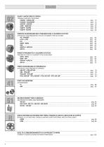
GIUNTI LIMITATORI DI COPPIA FRIZIONI OLEODINAMICHE E PNEUMATICHE A CILINDRO STATICO TORQUE-LIMITING COUPLINGS HYDRAULIC AND PNEUMATIC STATIC-CYLINDER TYPE CLUTCHES INNESTI PNEUMATICI A CILINDRO STATICO PNEUMATIC STATIC-CYLINDER TYPE COUPLINGS FRENI OLEODINAMICI E PNEUMATICI HYDRAULIC AND PNEUMATIC BRAKES PARTI ACCESSORIE DISCHI INTERNI ED ESTERNI PER FRENI, FRIZIONI E GIUNTI LIMITATORI DI COPPIA BRAKES, CLUTCHES AND TORQUE-LIMITING JOINTS INTERNAL AND EXTERAL DISKS SCELTA E DIMENSIONAMENTO DI UN PRODOTTO MWM CORRECT CHOICE & SIZING OF MWM COMPONENT .
Open the catalog to page 2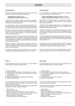
Nella nostra produzione, distinguiamo gli organi di trasmissione in base alia modalita di trasmissione della coppia: - trasmissione per attrito (frizioni) - trasmissione a dentini frontali (innesti) I giunti limitatori di coppia, essendodisponibilicon modellisia multidisco o con guarnizioni d’attrito, sia con modell ia dentini, rientrano in entrambe le categorie. Le frizioni possono essere comand ate oleod inamicamente o pneumaticamente e sono in gradodi accoppiare due cinemati-smi rotanti con velocita relative diverse (accoppiamenti dinamici) Gli innesti a dentini possono essere comandati come...
Open the catalog to page 3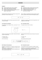
Poichè nella fase di innesto oltre ad accelerare le masse si deve trasmettere il momento costante, si ha: Since in addition to accelerating the masses during the coupling phase, a constant moment must also be transmitted, we have: Momento inseribile innesto o freno (a catalogo) Momento statico (coppia max trasmissibile) Momento di inserzione (teorico da calcolo) Momento costante di trasmissione (o coppia) del carico Momento di accelerazione sotto carico da 0 a n1 o da n1 a n2 giri Engagement coupling or braking moment (per catalog) Static moment (maximum transmissable couple) Engagement moment...
Open the catalog to page 4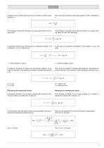
A questo punto si deve fare intervenire nei calcoli il numero di giri Now we have to introduce the rotary speed, R.P.M., indicated by al minuto n. n. Percalcolare il momento d’inerzia J di corpi rotanti intorno al loro The formula to calculate the moment of inertia J of a body rotat-asse si ha: ing about its axis is the following: Il momento d’inerzia per cilindri pieni con diametro esterno D e In the case of a cylinder of diameter D and length L in cm, we lunghezza L in cm si ottiene con: have: Il momento d’inerzia di masse con movimento rettilineo di un corpo a velocita (V) per mezzo di un...
Open the catalog to page 5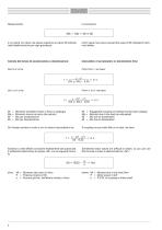
il cui valore non deve mai essere superiore al valore Mi indicato nelle tabelle tecniche per ogni grandezza which value must never exceed the value of Mi indicated in technical tables. Calcolo del tempo di accelerazione o decelerazione: Calculation of acceleration or deceleration time: Momento inseribile innesto o freno (a catalogo) Momento dovuto al carico (da calcolo) Mic per accelerazione Mic per decelerazione Engageable coupling or braking moment (per catalog) Moment due to the load (as calculated) Mic due to acceleration Mic due to deceleration Se l’innesto avviene a vuoto o con un carico...
Open the catalog to page 6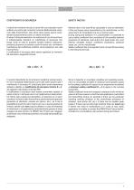
SAFETY FACTOR Il valore del momento dovuto al carico Mt così calcolato è però soltanto una stima del momento torcente effettivamente sostenuto dalla frizione/freno, tale valore deve essere perciò considerato esclusivamente come un valore nominale. Durante il dimensionamento e la selezione di una frizione/freno è indispensabile utilizzare un coefficiente di sicurezza che tenga conto di tutte le possibili variabili esterne (vibrazioni, presenza di sporco e/o polvere, picchi di carico, etc.) ed interne (oscillazioni del coefficiente di attrito, cali di pressione, etc.) alla frizione/freno. Il coefficiente...
Open the catalog to page 7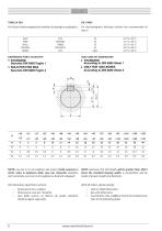
TABELLA OLII OIL TABLE Perfrizioni elettromagnetiche lamellari latipologia consigliata e: For electromagnetic disk-type clutches the recommended oil DIMENSIONI FORI E CHIAVETTE • SOLO PER FORI MAX Secondo DIN 6885 Foglio 2 • ONLY FOR MAX BORES According to DIN 6885 Sheet 2 NOTA: nei casi in cui la lunghezza del mozzo risulti superiore a 10/11 volte la larghezza della cava per chiavetta standard, verra praticato uno scarico di lunghezza e diametro adeguati All'ordinazione specificare sempre: - Dimensione foro o albero - Dimensione cava per chiavetta - Lato dello scarico, se diverso da quello standard....
Open the catalog to page 8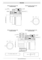
Posizione standard scarico per serie: Standard counterbore position for series: Posizione standard scarico per serie: Standard counterbore position for series:
Open the catalog to page 9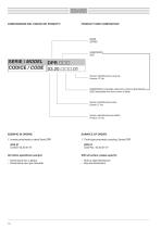
COMPOSIZIONE DEL CODICE DEI PRODOTTI PRODUCT CODE COMPOSITION SERIE Numero identificazione versione Version I.D. No. GRANDEZZA (ricavabile dalla prima colonna della tabella) SIZE (obtainable from first column of table) Numero identificazione serie Series I.D. No. Numero identificazione prodotto Product I.D. No. 1. Innesto pneumatico a denti Serie DPR 1. Tooth-type pneumatic coupling, Series DPR - Dimensione foro o albero - Dimensione cava per chiavetta With all orders, please specify: - Hole or shaft dimensions - Key-slot dimensions
Open the catalog to page 10All MWM FRENI-FRIZIONI catalogs and technical brochures
 Electromagnetic clucthes and brakes
162 Pages

- Friction brake
- Spring brake
- Disc brake
- Friction brake caliper
- Electromagnetic brake
- Friction clutch
- Disc brake caliper
- Spring brake caliper
- Electromagnetic clutch
- Hydraulic brake
- Pneumatic brake caliper
- Mechanical slip clutch
- Emergency brake
- Disc clutch
- Spring activated brake
- Hydraulic brake caliper
- Friction torque limiter