Catalog excerpts

# STARWAVE Shaping the future of 5G mmWave OTA testing Introducing StarWave, a compact, accurate and flexible far-field OTA testing solution for 5G devices Microwave Vision Group J
Open the catalog to page 1
haping a connected S society with 5G TABLE OF CONTENTS T he dawn of 5G antenna testing and its key challenges B est practice for 5G mmWave OTA testing P roven credentials – StarWave under test M VG StarWave Optimizes 5G Device Testing Processes The dawn of 5G is upon us and unlike transitioning between previous generations of mobile networks, this will be an all-encompassing global leap towards a digitally enhanced, completely connected, largely automated way of living. It is, to all intents and purposes, a dramatic overhaul and harmonization of the radio spectrum. This networked society...
Open the catalog to page 2
he dawn of 5G antenna T testing and its key challenges Enhanced mobile broadband The magnitude of what is deemed capable as we face the dawn of 5G is nothing short of inspiring, with autonomous factories and agricultural processes, self-driving cars, the convenience and comfort of a connected home, and even remote medical surgeries. Concepts such as these demonstrate the critical importance of full-system performance testing and, in particular, the accurate evaluation and analysis of antenna testing in order to deliver the wireless connection required for such revolutionary applications. To...
Open the catalog to page 3
To make steerable beams a viable and reliable method of transmission, base transceiver station (BTS) antennas are evolving from passive antenna to active antenna systems (AAS) with the integration of the remote radio head. The most favored AAS is the Massive MIMO concept, which many providers are already evolving towards in order to multiply the capacity of a wireless connection without the need for increased spectrum. CHALLENGE TWO: Wide bandwidths and mmWave frequencies To allow higher throughput and fully realize the 5G vision will mean harnessing the power of spectrum which has, until...
Open the catalog to page 4
Best practice tor 5G mmWave OTA testing 5G devices require an over-the-air (OTA) test method which creates a number of challenges in both the near-field and far-field when testing the latest antenna technology. 5G testing in the near-field may benefit from smaller chamber sizes. Nevertheless, the near-field technique does not allow for measurement of some performance parameters such as the Error Vector Magnitude (EVM) figure, according to the standard procedure today. In addition, the near-field technique requires near-field to far-field transformation and depends on phase and magnitude...
Open the catalog to page 5
In conclusion, best practice theory recommends 5G OTA testing of antennas under far-field conditions, which, given the expansive nature of such test facilities, poses the question: How to perform OTA testing in far-field conditions facing the four challenges mentioned previously? COMPACT ANTENNA TEST RANGE (CATR) Well known in the industry, this method approximates a plane wave in the QZ in which the amplitude and phase variation is below a user-specific tolerance. A CATR allows electrically large antennas to be measured at a significantly shorter distance than would be necessary in a...
Open the catalog to page 6
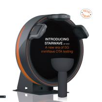
INTRODUCING STARWAVE BY MVG A new era of 5G mmWave OTA testing
Open the catalog to page 8
MVG brings to market a new generation of 5G mmWave OTA testing solutions, combining smart mechanical positioners with PWGs to create accurate direct far-field conditions in a compact system. StarWave, is composed of one or several (up to seven) PWG(s) attached at a 90° angle to a vertical disk, which rotates. In front of the disk, an electromagnetically transparent mast is mounted on an azimuth positioner to support and rotate a DUT. The interface used between the mast and the DUT depends on the device, with the possibility of inserting a chair for a person holding a device. StarWave...
Open the catalog to page 9
StarWave FR1 and StarWave FR2 simplified specifications Full spherical measurement system in direct FF conditions according to 3GPP IFF specification Number of PWGs supported: Maximum 7, with angular separation at 45° Anechoic chamber size: 4 x 4 x 4 (m) External radius of rotating PWG: 1475 mm Future options: 3D stereo camera for CAD generation and interface with post-processing/ simulation tools or understand the coordinate system of the device that you are testing. StarWave can be mounted on a turntable and rotated around a stationary DUT. PWG simplified specifications Model 1: PWG6 I...
Open the catalog to page 10
StarWave parameters at a glance Size of Radiating Surface Live end-to-end testing Distance to QZ from the Radiating Surface High Directivity Antenna Low/ Medium Directivity Antenna Wideband Operation Dual Polarisation Smart Positioning System A CLOSER LOOK AT STARWAVE Rotating structure Support base Plane wave generator front end 3D Stereo camera DUT positioning platform (azimuth rotation) Instrumentation motor cabling (RF / power / control)
Open the catalog to page 11
roven credentials – P StarWave under test PWG28 simulation figures - In the 2D views, the QZ is represented by a white circle. In the cuts, the QZ is represent in the white area. The simulation shows minimum amplitude and phase variation in the QZ area. PWG28 SIMULATION RESULTS MVG has proven the credentials of its StarWave PWG, a dual-polarized wideband PWG for direct far-field testing conditions, covering the 24.25 GHz to 29.5 GHz range (PWG28). Amplitude and phase variation The simulation test shown here presents the result of the PWG28 spherical QZ. It presents a diameter of 350 mm...
Open the catalog to page 12
COMPARISON AMONG STARWAVE, STARLAB 50 GHz AND SIMULATION To demonstrate the ability of StarWave to measure semi-directive devices, MVG chose its well-known QR18000, a closed boundary quad-ridge horn, operating between 10 and 40 GHz. This horn (see figure 5) presents a typical medium gain antenna radiation pattern (see figure 6 and 7). Typical 3D co-polarization radiation pattern Figure 6 Typical 3D cross-polarization radiation pattern
Open the catalog to page 13
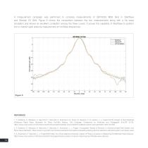
A measurement campaign was performed to compare measurements of QR18000 @28 GHz in StarWave and StarLab 50 GHz. Figure 8 shows the comparison between the two measurements along with a full wave simulation and shows an excellent correlation among the three curves. It proves the capability of StarWave to perform low to medium gain antenna measurement at mmWave frequencies. REFERENCE 1. F. Scattone, D. Sekuljica, A. Giacomini, F. Saccardi, A. Scannavini, N. Gross, E. Kaverine, P. O. Iversen, L. J. Foged (2019). Design of Dual Polarised Wideband Plane Wave Generator for Direct Far-Field...
Open the catalog to page 14All MVG catalogs and technical brochures
-
AEROLAB
6 Pages
-
StarBot 4300
6 Pages
-
SG Evo
8 Pages
-
Mini-Compact Range
4 Pages
-
+ANTENNA PRODUCT OVERVIEW
20 Pages
-
COMPACT RANGE OVERVIEW
16 Pages
-
SAR and HAC test benches
6 Pages
-
Absorber Product Overview
12 Pages
-
Positioning Equipment Catalog
140 Pages
-
RCS Pylon
8 Pages
-
RF Systems and Units
12 Pages
-
INSIGHT Brochure
12 Pages
-
catalogue_emc_2017
12 Pages
-
plaquette_rf_system_01_16
12 Pages
-
brochure_5g_06_17
12 Pages
-
AMS_catalog_
144 Pages
-
Absorber Catalog
48 Pages
-
SAR and HAC test benches
28 Pages
-
RF Safety Catalog
28 Pages
-
AMS
144 Pages
-
MVG Antenna Catalog
116 Pages
-
Power Combiners
4 Pages
Archived catalogs
-
Antenna Product Overview
20 Pages
-
FR8305
2 Pages
-
SG 3000F
6 Pages
-
SG 64
6 Pages
-
Pulse Modulator
2 Pages
-
Catalogue Antennas
116 Pages


