- Catalogs
- Murata Power Solutions
- NXF1 Series
NXF1 Series
1 /9Pages

NXF1 Series
1 /9Pages
Catalog excerpts
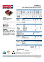
Isolated 1W Regulated Single Output DC-DC Converters Single isolated output Voltage range 3kVDC isolation ‘Hi-Pot Test’ Reflected ripple current INPUT CHARACTERISTICS Isolation Capacitance Output Current Output Voltage Nominal Input Voltage SELECTION GUIDE Continuous operation, 3.3V input types Continuous operation, 5V input types 3.3V Input types 5V Input types OUTPUT CHARACTERISTICS Parameter SMD construction Patent protected Short circuit protection Voltage set point accuracy Rated power The NXF1 series of DC-DC converters is used where a tightly regulated supply is required. They are ideal for situations where the input voltage is not tightly controlled. The single rail regulated output makes the ideal choice to power sensors, such as pressure transducers, hall effect sensors and mass airflow sensors. Line regulation Load regulation (10% load to rated load) 3.3V output types 5V output types ABSOLUTE MAXIMUM RATINGS Short-circuit protection Input voltage VIN, NXF1S03 types Input voltage VIN, NXF1S05 types Continuous and auto recovery 4V 7V ISOLATION CHARACTERISTICS Parameter Isolation test voltage Resistance Production tested for 1 second Qualification tested for 1 minute Viso= 1kVDC GENERAL CHARACTERISTICS Parameter Switching frequency TEMPERATURE CHARACTERISTICS Parameter Specification Conditions See derating graphs Storage Product temperature above ambient Cooling For full details go to www.murata-ps.com/rohs 3.3V input types 5V input type Free air convection Min. 3.3V Input types 5V input types 1. Components are supplied in tape and reel packaging, please refer to package specification section. Orderable part numbers are NXF1SXXXXMC-R7 (160 pieces per reel), or NXF1SXXXXMC-R13 (740 pieces per reel). 2. Calculated using MIL-HDBK-217F with nominal input voltage at full load. 3. NXF1S0303MC is in preliminary stages. All specifications typical at TA=25°C, nominal input voltage and rated output current unless otherwise specified.
Open the catalog to page 1
NXF1 Series Isolated 1W Regulated Single Output DC-DC Converters TECHNICAL NOTES ISOLATION VOLTAGE ‘Hi Pot Test’, ‘Flash Tested’, ‘Withstand Voltage’, ‘Proof Voltage’, ‘Dielectric Withstand Voltage’ & ‘Isolation Test Voltage’ are all terms that relate to the same thing, a test voltage, applied for a specified time, across a component designed to provide electrical isolation, to verify the integrity of that isolation. Murata Power Solutions NXF1 series of DC-DC converters are all 100% production tested at 3kVDC for 1 second and has been qualification tested at 3.3kVDC for 1 minute. A question commonly...
Open the catalog to page 2
Murata Power Solutions NXF1 Series Isolated 1W Regulated Single Output DC-DC ConvertersAPPLICATION NOTES (continued) Capacitive loading and start up Typical start up times for this series, with a typical input voltage rise time of 2.2ps and output capacitance of 10^F, are shown in the table below. In most applications an output capacitance is 10^F is usually sufficient, the maximum allowable output capacitance is as follows. NXF1S0505MC Differential Mode Noise Test Schematic
Open the catalog to page 3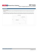
NXF1 Series Isolated 1W Regulated Single Output DC-DC Converters APPLICATION NOTES Short Circuit Performance The NXF1 series short circuit protection is continuous, the NXF1S0303MC and NXF1S0305MC will auto restart under all datasheet operating conditions after a short circuit. For the NXF1S0505MC, the short circuit protection is continuous, however, at higher temperatures or output current, the part will not automatically restart following a short circuit condition. At higher temperatures or higher load as shown in the below graph, the input power must be re-cycled for the part to restart. NXF1S0505MC...
Open the catalog to page 4
Murata Power Solutions NXF1 Series Isolated 1W Regulated Single Output DC-DC Converters EFFICIENCY VS LOAD
Open the catalog to page 5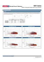
Murata Power Solutions NXF1 Series Isolated 1W Regulated Single Output DC-DC ConvertersEMC FILTERING AND SPECTRA FILTERING The following filter circuit and filter table shows the input filters typically required to meet conducted emissions limits for EN 55022 curve B using Quasi-Peak (pink line) and average (green line) detectors according to CISPR 22. The following plots show measurements of the positive (L1) and negative (L2) inputs for both Quasi-peak limit B adherence and Average limit B adherence. Power Source
Open the catalog to page 6
Murata Power Solutions NXF1 Series Isolated 1W Regulated Single Output DC-DC Converters EMC FILTERING AND SPECTRA (continued)
Open the catalog to page 7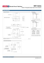
Murata Power Solutions NXF1 Series Isolated 1W Regulated Single Output DC-DC ConvertersPACKAGE SPECIFICATIONS Pin Connections Mechanical Dimensions NA - Not available for electrical connection. All dimensions in mm (inches), Controlling dimension is mm. Tolerances (unless otherwise stated) ±0.20 (0.008). Recommended Footprint Details
Open the catalog to page 8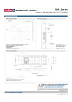
NXF1 Series Isolated 1W Regulated Single Output DC-DC Converters TAPE & REEL SPECIFICATIONS REEL OUTLINE DIMENSIONS REEL PACKAGING DETAILS 30.4 [1.197] MAX# GOODS ENCLOSURE SECTION TAPE & REEL SPECIFICATIONS SHALL CONFORM WITH CURRENT EIA-481 STANDARD UNLESS OTHERWISE STATED ALL DIMENSIONS IN mm (INCHES) CONTROLLING DIMENSION IS mm # MEASURED AT HUB ## SIX EQUI-SPACED SLOTS ON 180mm/7” REEL Carrier tape pockets shown are illustrative only - Refer to carrier tape diagram for actual pocket details. Reel Quantity: 7” - 160 or 13” -740 TAPE OUTLINE DIMENSIONS COVER TAPE Tape & Reel specifications...
Open the catalog to page 9All Murata Power Solutions catalogs and technical brochures
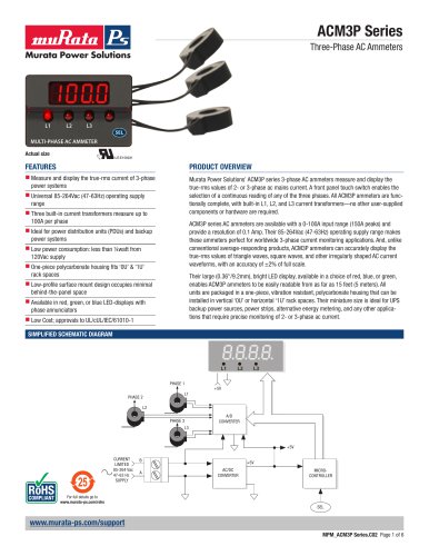 ACM3P Series
6 Pages
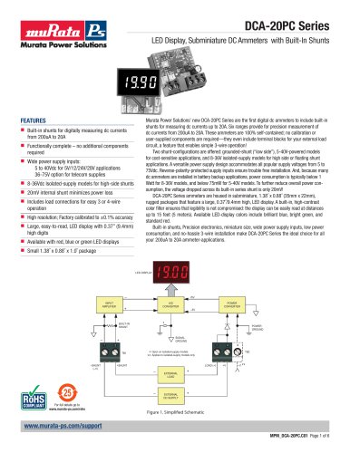 DCA-20PC Series
6 Pages
 DMS-20PC-1-LM-BF-C
2 Pages
 ACA-20RM-1-AC3-RL-C
5 Pages
 DMR20-4/20 Series
5 Pages
 DMS-20LCD-4/20 Series
6 Pages
 OKI-78SR-E Series
20 Pages
 MGJ6 14mm Series
12 Pages
 DC-DC Converters
28 Pages
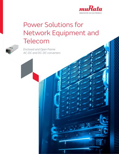
 Power solutions
6 Pages

Archived catalogs
 Digital Panel Meters
16 Pages
 1200RS Series
3 Pages
 DMS Accessories
4 Pages
 D2U5T-H3-7000-54-HU4C
8 Pages
 OKL-T_1-W12N-C
2 Pages


- Transformer
- Dry transformer
- Encapsulated transformer
- Power transformer
- Current sensor
- Industrial transformer
- AC current sensor
- Transformer for industrial applications
- RoHS transformer
- Current transducer
- Compact transformer
- Through-hole transformer
- Electronic transformer
- Precision current transducer
- Precision current sensor
- Transformer current sensor
- Board-mount current sensor
- Transformer current transducer
- High-accuracy current transducer
- High-accuracy current sensor