- Catalogs
- Murata Power Solutions
- DMR20-4/20 Series
DMR20-4/20 Series
1 /5Pages

DMR20-4/20 Series
1 /5Pages
Catalog excerpts
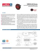
DMR20-4/20 Series Loop-Powered, 4-20 mA LED Display Process Monitors with 2.5V Loop Drop FEATURES 2.5V maximum loop-drop (125 Ω burden) for red LED model! High-quality, 20-turn, span (gain) and Self-powered directly from 4-20 mA current zero (offset) loop, no external power source needed Fits round 1.20 inch [30.5 mm] cutouts; less than 1.00 inch [<25.4 mm] behind-the-panel depth Easy-to-read, 0.30 inch [7.6 mm] high LED digits with excellent display brightness; available in red or green LEDs Supplied with EPDM rubber gasket and hex nut High-quality, 20-turn, span (gain) and zero (offset) adjustments Gold-plated DIP-switch for range and decimal points: Reliable screw-terminal input connections Rugged, polycarbonate, one-piece package Protected against dust and water submersion to IP67/NEMA 6 Murata’s new DMR20-4/20 loop-powered digital process monitors feature a large, easy-to-read, bright LED display. All operating power is derived directly from the current loop itself—no external power source is required! The large, 0.30 [7.6 mm] digits exhibit uniform intensity over the entire 4-20 mA operating range. Unlike other loop-powered LED displays, the total maximum loop voltage drop for the red LED model is 2.5V! Users no longer have to settle for difficult-to-read LCD displays in loop-powered applications. Both gain (span) and offset (zero) adjustments are performed with on-board, precision, 20-turn potentiometers. All decimal-point and range-change selections are made on a six-position DIP switch featuring vibration-resistant, gold-plated contacts. Unlike competitive meters, there are no jumpers or solder gaps to open or close. Connections to the current loop are made via a reliable, two-position, screw-type terminal block. The DMR20-4/20’s DIP-switch and potentiometers accommodate hundreds of different input-current/output-reading combinations. This versatility eliminates the need to order more costly, long-lead-time customs meters in applications in which several different-range meters are required. The round plastic housing fits standard 1.20” [30.5mm] panel cutouts. An EPDM rubber gasket and hex nut simplify installation and provide IP67/NEMA 6 protection to environmental dirt and moisture. SIMPLIFIED SCHEMATIC DIAGRAM
Open the catalog to page 1
muRala. Mu rata Power Solutions Performance/Functional Specifications Typical at Ta = +25°C, unless otherwise noted. Ordering Information DMR20-4/20S-R-C Unipolar, loop-powered red LED meter DMR20-4/20S-G-C Unipolar, loop-powered green ED meter DMR20-4/20B-R-C Unipolar, loop-powered red LED meter Note: An M30 x 1.5 nylon metric hex nut and EPDM sealing gasket are supplied with each meter. The “-C” suffix indicates RoHS compliance Panel Knockout Tools: DMR20-1-KP 1.22” [30.9 mm] punch (no keying notch) DMR20-2-KP 1.21” [30.7 mm] punch with 4 keying notches DMR20-3-KP Keyway Punch tool Examples...
Open the catalog to page 2
Murata Power Solutions Subminiature 4-20 mA Loop-Powered 3% Digit LED Process Monitors This example is not as straightforward as the previous two. Notice that 12 mA is exactly halfway between 4 mA and 20 mA. If we assume that the input could go up to 20 mA, the display reading would then be: 2 x. 250 or .”500.” From Table 1 we can now select DIP-switch setting #4 and enable DPI by setting SW1 to Off and SW2 to On. Apply 4 mA and adjust R3 so the display reads ”000.” Apply 12 mA and adjust R7 so the display reads ”250.” DMR20-4/20B (Bipolar Reading Model) The DMR20-4/20B's zero-offset circuit...
Open the catalog to page 3
DMR20-4/20 Series Subminiature 4-20 mA Loop-Powered 3½ Digit LED Process Monitors CONNECTION DIAGRAM Figure 2 Typical DMR20-4/20 Connection Diagram INSTALLATION DIAGRAM Figure 3 Panel Installation
Open the catalog to page 4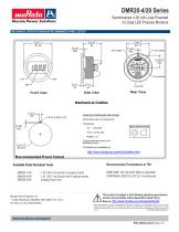
Murata Power Solutions Subminiature 4-20 mA Loop-Powered 3% Digit LED Process Monitors MECHANICAL SPECIFICATIONS AND RECOMMENDED PANEL CUTOUT Mechanical Outline TMIKO ANCLE PtOJECIION ©d UNLESS OTHERWISE SPECIFIED: Dimensions are in Inches [mm] Tolerances: XX t.02 [0 .5] XXX 2.010 [.25] Angles: ±2’ Components are showi for Reference Only 3D Models are available at: Recommended Panel Cutout Recommended Terminations at TB1 WIRE SIZE: 18 to 26 AWG (Solid or stranded) STRIPPING LENGTH: 0.20” [5.1 mm] Nominal DMR20-1-KP 1.22” [30.9 mm] punch (no keying notch) DMR20-2-KP 1.21” [30.7 mm] punch...
Open the catalog to page 5All Murata Power Solutions catalogs and technical brochures
 ACM3P Series
6 Pages
 DCA-20PC Series
6 Pages
 DMS-20PC-1-LM-BF-C
2 Pages
 ACA-20RM-1-AC3-RL-C
5 Pages
 DMS-20LCD-4/20 Series
6 Pages
 OKI-78SR-E Series
20 Pages
 MGJ6 14mm Series
12 Pages
 NXF1 Series
9 Pages
 DC-DC Converters
28 Pages
 Power solutions
6 Pages

Archived catalogs
 Digital Panel Meters
16 Pages
 1200RS Series
3 Pages
 DMS Accessories
4 Pages
 D2U5T-H3-7000-54-HU4C
8 Pages
 OKL-T_1-W12N-C
2 Pages


- Transformer
- Dry transformer
- Encapsulated transformer
- Power transformer
- Current sensor
- Industrial transformer
- AC current sensor
- Transformer for industrial applications
- RoHS transformer
- Current transducer
- Compact transformer
- Through-hole transformer
- Electronic transformer
- Precision current transducer
- Precision current sensor
- Transformer current sensor
- Board-mount current sensor
- Transformer current transducer
- High-accuracy current transducer
- High-accuracy current sensor