
- Catalogs
- Murata Electronics
- Radial Lead Type Monolithic Ceramic Capacitors


- Products
- Catalogs
- News & Trends
- Exhibitions
Radial Lead Type Monolithic Ceramic Capacitors

Radial Lead Type Monolithic Ceramic Capacitors
- Part Numbering: Details the structure of part numbers, including product ID, series, terminal, capacitance, tolerance, temperature characteristics, and rated voltage.
- Series Specifications: Includes RCE, RHE, and RDE series, each with specific temperature and voltage ratings. The RCE series is suitable for automotive use up to 125°C, while the RHE series can handle up to 150°C.
- Temperature Characteristics: Discusses different types such as C0G/U2J, X7R/X7S, and X8G/X8L, with their respective temperature ranges and capacitance change coefficients.
- Specifications and Test Methods: Provides detailed testing procedures and standards for each series.
- Marking and Packaging: Explains the marking codes for capacitance, voltage, and temperature characteristics, along with packaging options like ammo pack and bulk.
- Compliance and Caution: Emphasizes the importance of adhering to specified ratings and cautions to prevent damage such as smoking or burning. It also highlights the need for approval of product specifications before ordering.
- EU RoHS Compliance: All products comply with the European Directive 2011/65/EU, restricting hazardous substances in electrical and electronic equipment.
- Temperature and Voltage Ratings: Specific ratings are provided for different series, crucial for selecting the appropriate capacitor for specific applications.
- Handling and Storage: Detailed cautions are provided to ensure safe handling, storage, and operation of the capacitors.
- Operational Life: Capacitors are tested at 125±3°C for 1,000±12 hours. Post-test measurements are taken after a 24-hour rest at room conditions.
- Biased Humidity: Capacitors are exposed to 85±3°C and 80-85% humidity for 1,000±12 hours, followed by a 24-hour rest period.
- Moisture Resistance: Involves 10 cycles of heat and humidity treatment, with post-test measurements after a 24-hour rest.
- Temperature Cycling: Capacitors undergo 1,000 cycles of temperature changes, with specific time and temperature settings.
- High Temperature Exposure: Capacitors are stored at 150±3°C for 1,000±12 hours, followed by a 24-hour rest.
- Capacitance Temperature Characteristics: Capacitance change is measured after 5 minutes at each specified temperature step. The temperature coefficient is determined using the capacitance measured in step 3 as a reference. Capacitance drift should be within ±0.2% or ±0.05pF.
- Terminal Strength: Tensile and bending strength tests are conducted to ensure terminations are not broken or loosened.
- Operational Life: Capacitors are tested at high temperatures and voltages for extended periods to assess durability. Capacitance change should be within ±12.5%.
- Biased Humidity: Tests are conducted at high humidity and temperature to evaluate performance under moisture exposure. Capacitance change should be within ±12.5%.
- Thermal Shock: Capacitors undergo rapid temperature changes to test resilience. Capacitance change should be within ±5% or ±0.5pF.
- Resistance to Soldering Heat: Capacitors are exposed to high temperatures to test soldering heat resistance. Capacitance change should be within ±2.5% or ±0.25pF.
- Vibration and Mechanical Shock: Tests simulate mechanical stresses to ensure structural integrity. Capacitance should remain within specified tolerance.
- Resistance to Solvents: Capacitors are exposed to various solvents to test chemical resistance. No defects should be observed.
- All tests are conducted under specified room conditions: Temperature 15 to 35°C, Relative humidity 45 to 75%, and Atmospheric pressure 86 to 106kPa.
- It is crucial to read the ratings and cautions for storage, operating, soldering, mounting, and handling to prevent damage.
- Small size with large capacitance.
- Low Equivalent Series Resistance (ESR) and Equivalent Series Inductance (ESL), suitable for high-frequency applications.
- Maximum temperature capability of 150°C, with a cumulative time limit of 2000 hours at this temperature.
- Compliance with AEC-Q200 and ISO7637-2 surge test requirements.
- Lead-Free (LF) and Halogen-Free (HF) compliant.
- Flow soldering and welding are available, but re-flow soldering is not.
- Copper wire can be used in the welding process upon request.
- Rated Voltage: DC50V to DC100V.
- Temperature Characteristics: X8G and X8L.
- Capacitance Tolerance: ±5% for X8G and ±10% for X8L.
- Dimensions and lead style codes are provided for various configurations.
- Operational Life: Capacitors are tested at 150% of rated voltage for 1,000 hours at 150°C.
- Biased Humidity: Tested at 85°C and 80-85% humidity for 1,000 hours.
- Moisture Resistance: Subjected to 24-hour cycles of varying temperature and humidity.
- Temperature Cycling: Exposed to cycles between -55°C and 150°C.
- High Temperature Exposure: Stored at 150°C for 1,000 hours.
- Solderability and Resistance to Soldering Heat: Evaluated by dipping in solder and assessing coating uniformity.
- Mechanical Shock and Vibration: Tested for durability under mechanical stress.
- Part Number: Unique identifier for each capacitor.
- Temperature Characteristics: Denoted by codes such as U2J and X7R/X7S, indicating the dielectric material and its properties.
- Rated Voltage: Ranges from 25Vdc to 1000Vdc, indicating the maximum voltage the capacitor can handle.
- Capacitance: Values range from 10pF to 94000pF, with a tolerance of ±5% or ±10%.
- Dimensions: Provided in LxW (mm) and T (mm), indicating the size of the capacitor.
- Lead Space: The distance between the leads, typically 5.0mm or 2.5mm.
- Lead Style Code: Codes such as K1, M1, P1, S1, B1, and E1, indicating the style and packaging of the leads.
The document provides detailed specifications for a range of capacitors, including dimensions, lead style codes, DC rated voltage, temperature characteristics, and capacitance tolerance. Capacitors are marked with specific codes indicating their characteristics and ratings.
Dimensions and Lead Style:
Capacitors are categorized by dimensions (LxW, T, F) and lead style codes (K1, M1, B1, E1). The document lists various part numbers with corresponding specifications such as capacitance, voltage, and tolerance.
Temperature and Voltage Characteristics:
Capacitors exhibit specific temperature characteristics (X7T) and are rated for voltages of 250V, 450V, and 630V. The document includes tables showing capacitance changes with temperature and DC voltage.
Test Methods and Specifications:
Several tests are outlined to ensure capacitor reliability, including vibration resistance, terminal strength, capacitance temperature characteristics, insulation resistance, dielectric strength, and solderability. Each test has specific conditions and acceptance criteria.
Performance Data:
Graphs illustrate capacitance changes over temperature, DC voltage, and time (aging). Impedance-frequency characteristics are also provided for different capacitance values.
Packaging Information:
Capacitors are available in bulk or tape carrier packaging, with minimum quantities specified for each type.
Important Notes:
The document emphasizes the importance of reading ratings and cautions related to storage, operating conditions, and handling to prevent damage. It also notes that the catalog contains typical specifications, and approval of product specifications is required before ordering.
Catalog excerpts

!Note • Please read rating and !CAUTION (for storage, operating, rating, soldering, mounting and handling) in this catalog to prevent smoking and/or burning, etc. • This catalog has only typical specications. Therefore, please approve our product specications or transact the approval sheet for product specications before ordering. Radial Lead Type Monolithic Ceramic Capacitors
Open the catalog to page 1
!Note • Please read rating and !CAUTION (for storage, operating, rating, soldering, mounting and handling) in this catalog to prevent smoking and/or burning, etc. • This catalog has only typical specications. Therefore, please approve our product specications or transact the approval sheet for product specications before ordering. EU RoHS Compliant All the products in this catalog comply with EU RoHS. EU RoHS is "the European Directive 2011/65/EU on the Restriction of the Use of Certain Hazardous Substances in Electrical and Electronic Equipment." For more details, please refer to our website...
Open the catalog to page 2
d^Note * Please read rating and ^CAUTION (for storage, operating, rating, soldering, mounting and handling) in this catalog to prevent smoking and/or burning, etc. G49E.pdf • This catalog has only typical specifications. Therefore, please approve our product specifications or transact the approval sheet for product specifications before ordering. Mat *| 2 201 4 Part Numbering Reference Data (Typical Example) Temperature Compensating Type, C0G/U2J Characteristics 6 High Dielectric Constant Type, X7R/X7S Characteristics 11 • Specifications and Test Methods - 14 Temperature Compensating Type, X8G...
Open the catalog to page 3
!Note • Please read rating and !CAUTION (for storage, operating, rating, soldering, mounting and handling) in this catalog to prevent smoking and/or burning, etc. • This catalog has only typical specications. Therefore, please approve our product specications or transact the approval sheet for product specications before ordering. o Part Numbering Radial Lead Type Monolithic Ceramic Capacitors (Part Number) qProduct ID wSeries/Terminal Product ID Radial Lead Type Monolithic Ceramic Capacitors 125°C max. (for Automotive) (DC25V-DC1kV) Radial Lead Type Monolithic Ceramic Capacitors 150°C max. (for...
Open the catalog to page 4
d^NotG * Please read rating and ^CAUTION (for storage, operating, rating, soldering, mounting and handling) in this catalog to prevent smoking and/or burning, etc. C49 E.pdf • This catalog has only typical specifications. Therefore, please approve our product specifications or transact the approval sheet for product specifications before ordering. ^ ^ 4 [\|] Continued from the preceding page.
Open the catalog to page 5
!Note • Please read rating and !CAUTION (for storage, operating, rating, soldering, mounting and handling) in this catalog to prevent smoking and/or burning, etc. • This catalog has only typical specications. Therefore, please approve our product specications or transact the approval sheet for product specications before ordering. Radial Lead Type Monolithic Ceramic Capacitors 1. Small size and large capacitance 2. Low ESR and ESL suitable for high frequency 3. Meet AEC-Q200, ISO7637-2 (surge test) requirement 4. Meet LF (Lead Free) and HF (Halogen Free) 5. Flow soldering and welding are available....
Open the catalog to page 6
!Note • Please read rating and !CAUTION (for storage, operating, rating, soldering, mounting and handling) in this catalog to prevent smoking and/or burning, etc. • This catalog has only typical specications. Therefore, please approve our product specications or transact the approval sheet for product specications before ordering. Continued from the preceding page. ∗ Coating extension does not exceed the end of the lead bend. · Lead Wire: Solder Coated CP Wire (in mm) Dimensions code: 4 Lead style code: K1 F±0.8 ∗ Coating extension does not exceed the end of the lead bend. · Lead Wire: Solder...
Open the catalog to page 7
!Note • Please read rating and !CAUTION (for storage, operating, rating, soldering, mounting and handling) in this catalog to prevent smoking and/or burning, etc. • This catalog has only typical specications. Therefore, please approve our product specications or transact the approval sheet for product specications before ordering. c Marking Rated Voltage Dimensions Code Temp. Char. Nominal Capacitance Capacitance Tolerance Temperature Characteristics Marked with code (C0G char.: A, X7S/X7R char.: C, U2J char.: U) A part is omitted (Please refer to the marking example.) Under 100pF: Actual value...
Open the catalog to page 8
!Note • Please read rating and !CAUTION (for storage, operating, rating, soldering, mounting and handling) in this catalog to prevent smoking and/or burning, etc. • This catalog has only typical specications. Therefore, please approve our product specications or transact the approval sheet for product specications before ordering. Continued from the preceding page. Temp. Char. Rated Voltage Lead Style Code Bulk Lead Style Code Taping Part Number Continued on the following page.
Open the catalog to page 9
!Note • Please read rating and !CAUTION (for storage, operating, rating, soldering, mounting and handling) in this catalog to prevent smoking and/or burning, etc. • This catalog has only typical specications. Therefore, please approve our product specications or transact the approval sheet for product specications before ordering. Continued from the preceding page. Temp. Char. Rated Voltage Lead Style Code Bulk Lead Style Code Taping Part Number Continued on the following page.
Open the catalog to page 10
!Note • Please read rating and !CAUTION (for storage, operating, rating, soldering, mounting and handling) in this catalog to prevent smoking and/or burning, etc. • This catalog has only typical specications. Therefore, please approve our product specications or transact the approval sheet for product specications before ordering. Continued from the preceding page. Temp. Char. Rated Voltage Lead Style Code Bulk Lead Style Code Taping Part Number Continued on the following page.
Open the catalog to page 11All Murata Electronics catalogs and technical brochures
 High Voltage Resistors
2 Pages
 XMSSJE3G0PA-003
5 Pages
 MURATA PRODUCTS Lineup 2018
164 Pages
 Murata Products for Automotive
13 Pages
 MURATA PRODUCTS Lineup
150 Pages
 MURATA PRODUCTS Lineup
136 Pages
 Ceramic Resonators "CERALOCK®"
46 Pages
 Piezoelectric Sound Components
28 Pages
 Chip Monolithic Ceramic Capacitors
182 Pages
 Trimmer Capacitors
39 Pages
 MEMS Sensors
4 Pages
 Ceramic Resonators CERALOCK®
32 Pages
 EMI Suppression Filters for AC
27 Pages
 Magnetic Switch
3 Pages
 Chip Multilayer LC Filters
9 Pages
 SAW Traps
1 Page


Archived catalogs
 Rotary Position Sensors_2015
26 Pages
 NTC Thermistors_2020
37 Pages
 NTC Thermistors_2012
40 Pages
 Chip Inductors (Chip Coils)_2019
274 Pages
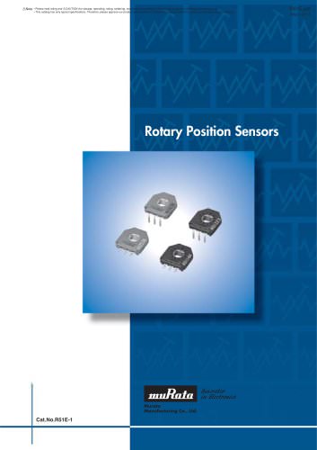 Rotary Position Sensors_2013
23 Pages
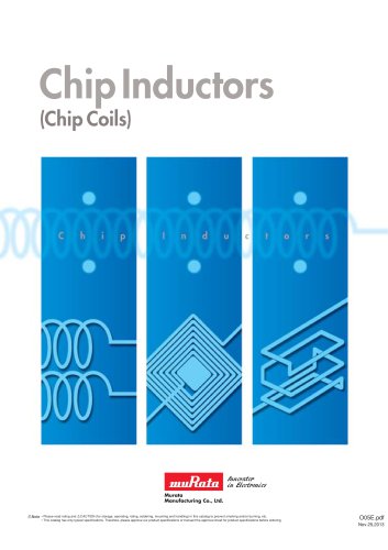 Chip Inductors (Chip Coils)_2013
249 Pages
 Pyroelectric Infrared Sensors
22 Pages
 Chip Monolithic Ceramic Capacitors
220 Pages
 Trimmer Potentiometers
59 Pages
 Crystal Resonator
3 Pages
 MURATA PRODUCTS 2010-2011
423 Pages
 NTC/PTC Thermistors for Automotive
71 Pages
 Trimmer Capacitors
44 Pages


