- Catalogs
- Murata Electronics
- Radial Lead Type Monolithic Ceramic Capacitors
Radial Lead Type Monolithic Ceramic Capacitors
1 /39Pages

Radial Lead Type Monolithic Ceramic Capacitors
1 /39Pages
Catalog excerpts

Cat.No.C49E-20 Radial Lead Type Monolithic Ceramic Capacitors
Open the catalog to page 1
for EU RoHS Compliant • All the products in this catalog comply with EU RoHS. • EU RoHS is "the European Directive 2002/95/EC on the Restriction of the Use of Certain Hazardous Substances in Electrical and Electronic Equipment". • For more details, please refer to our website 'Murata's Approach for EU RoHS' (http://www.murata.com/info/rohs.html).
Open the catalog to page 2
Part Numbering 2 RPE Series (DC25V-DC100V) 3 Marking 4 Temperature Compensating Type, C0G Characteristics 5 High Dielectric Constant Type, X7R Characteristics 8 High Dielectric Constant Type, Y5V Characteristics 10 Specifications and Test Methods 11 RPE Series Small Size, Large Capacitance (DC50V) 14 Marking 14 Specifications and Test Methods 15 RH Series 150 deg. C max. (for Automotive) (DC50V-DC100V) 17 Marking 18 Specifications and Test Methods 20 RDE Series (Only for Commercial Use) (DC250V-DC630V) 22 Marking 23 Specifications and Test Methods 25 RPE Series Characteristics Data (Typical Example)...
Open the catalog to page 3
2 (Part Number) w qProduct ID wSeries/Terminal RP RH RD E E/D E Radial Lead Type Monolithic Ceramic Capacitors (DC25V-DC100V) Radial Lead Type Monolithic Ceramic Capacitors (Only for Commercial Use) (DC250V-DC630V) Radial Lead Type Monolithic Ceramic Capacitors 150°C max. (for Automotive) (DC50V-DC100V) Product ID Series/Terminal RP q E e R7 r 1H t 104 u 2 i M1 y K o A03 !0 A tCapacitance Expressed by three-digit alphanumerics. The unit is pico-farad (pF). The first and second figures are significant digits, and the third figure expresses the number of zeros which follow the two numbers. If there...
Open the catalog to page 4
RPE Series (DC25V-DC100V) n Features 1. The RPE series capacitors have small dimensions, large capacitance, and a capacity volume ratio of 10 micro F/cm cubed, close to that of electrolytic capacitors. These do not have polarity. 2. These have excellent frequency characteristics and due to these small internal inductance are suitable for high frequencies. 3. These are not coated with wax so there is no change in their exterior appearance due to the outflow of wax during soldering or solvent during cleansing. 4. These are highly inflammable, having characteristics equivalent to the UL94V-0 standard....
Open the catalog to page 5
4 Individual Specification Code App Bpp Zpp Individual Specification Code Except App Bpp Zpp 3, 4, 8 5, 6, 7 Temperature Characteristics Nominal Capacitance Capacitance Tolerance Rated Voltage Manufacturer's Identification 2 102J 5A 222K 224Z 682 J5A 333 J5A 103 J5A M M M M 224 K5C 225 K5C 684 K5C M M M 474 Z5F M Under 100pF: Actual value 100pF and over: marked with 3 figures — — Marked with code Marked with code (C0G char.: A, X7R char.: C, Y5V char.: F) A part is omitted (Please refer to the marking example.) Marked with code (DC25V: 2, DC50V: 5, DC100V: 1) A part is omitted (Please refer to...
Open the catalog to page 6
The capacitance change should be measured after min. at each specified temperature stage. (1) Temperature Compensating Type The temperature coefficient is determined using the capacitance measured in step 3 as a reference. When cycling the temperature sequentially from step 1 through 5 (-55 to +125°C) the capacitance should within the specified tolerance for the temperature coefficient and capacitance change as shown in Table A. The capacitance drift is calculated by dividing the differences between the maximum and minimum measured values in step 1, 3 and 5 by the cap. value step 3. (2) High...
Open the catalog to page 13
No. 14 Item Temperature and Immersion Cycle Dielectric Strength (Between Terminals) Temperature Compensating Type High Dielectric Constant Type No defects or abnormalities Char. X7R : 0.025 max. Char. Y5V : 0.05 max. Char. X7R : Within T7.5% Char. Y5V : Within T20% Test Method First, repeat the following temperature/time cycle times : lowest operating temperature T3°C/30T3 min. ordinary temperature/3 min. max. highest operating temperature T3°C/30T3 min. ordinary temperature/3 min. max. Next, repeat twice the successive cycles of immersion, each cycle consisting of immersion in a fresh water...
Open the catalog to page 14
Table A No. 18 Item Solvent Resistance Marking Temperature Compensating Type High Dielectric Constant Type Legible Test Method The capacitor should be fully immersed, unagitated, reagent at 20 to 25°C for 30T5 sec. and then remove gently. Marking on the surface of the capacitor should immediately be visually examined. Reagent: • Isopropyl alcohol Capacitance Change from 25°C (%) -55°C -30°C -10°C Max. Min. Max. Min. Max. Min. *1: Nominal values denote the temperature coefficient within a range of 25 to 125°C 15 Humidity (Steady State) Appearance No defects or abnormalities Set the capacitor for...
Open the catalog to page 15
14 2 RPE Series Small Size, Large Capacitance (DC50V) n Features 1. The RPE series capacitors have small dimensions, large capacitance, and a capacity volume ratio of 10 micro F/cm cubed, close to that of electrolytic capacitors. These do not have polarity. 2. These have excellent frequency characteristics and due to these small internal inductance are suitable for high frequencies. 3. These are not coated with wax so there is no change in their exterior appearance due to the outflow of wax during soldering or solvent during cleansing. 4. These are highly inflammable, having characteristics equivalent...
Open the catalog to page 16
The capacitor should be firmly soldered to the supporting lead wire and vibrated at a frequency of 10 to 55Hz, 1.5mm in total amplitude, with about minute rate of vibration change from 10Hz to 55Hz back to 10Hz. Apply for a total of 6 hrs., 2 hrs. each mutually perpendicular directions. 10 Vibration Resistance Appearance No defects or abnormalities As in the figure, fix the capacitor body, apply the gradually to each lead in the radial direction of the capacitor until reaching 10N and then keep the force applied for 10T1 sec. 9 Terminal Strength Tensile Strength Termination not to be broken or...
Open the catalog to page 17
The capacitor should be fully immersed, unagitated, reagent at 20 to 25 °C for 30T5 sec. and then remove gently. Marking on the surface of the capacitor should immediately be visually examined. Reagent : • Isopropyl alcohol 17 Solvent Resistance Appearance No defects or abnormalities Apply a DC voltage of 150% of the rated voltage 1000 W Y 48 0 hrs. at the maximum operating temperature. Remove and set for 48T4 hrs. at room temperature, then measure. (Charge/Discharge current V 50mA) • Pretreatment Apply test voltage for 1 hr., at test temperature. Remove and set for 48T4 hrs. at room temperature....
Open the catalog to page 18All Murata Electronics catalogs and technical brochures
 High Voltage Resistors
2 Pages
 XMSSJE3G0PA-003
5 Pages
 MURATA PRODUCTS Lineup 2018
164 Pages
 Murata Products for Automotive
13 Pages
 MURATA PRODUCTS Lineup
150 Pages
 MURATA PRODUCTS Lineup
136 Pages
 Ceramic Resonators "CERALOCK®"
46 Pages
 Piezoelectric Sound Components
28 Pages
 Chip Monolithic Ceramic Capacitors
182 Pages
 Trimmer Capacitors
39 Pages
 MEMS Sensors
4 Pages
 Ceramic Resonators CERALOCK®
32 Pages
 EMI Suppression Filters for AC
27 Pages
 Magnetic Switch
3 Pages
 Chip Multilayer LC Filters
9 Pages
 SAW Traps
1 Page


Archived catalogs
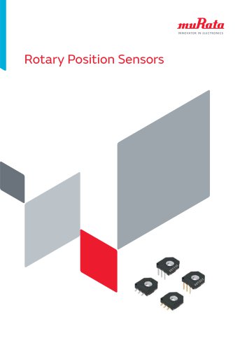 Rotary Position Sensors_2015
26 Pages
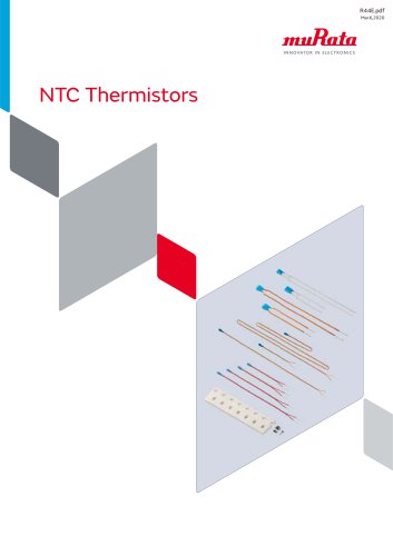 NTC Thermistors_2020
37 Pages
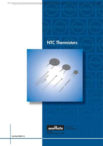 NTC Thermistors_2012
40 Pages
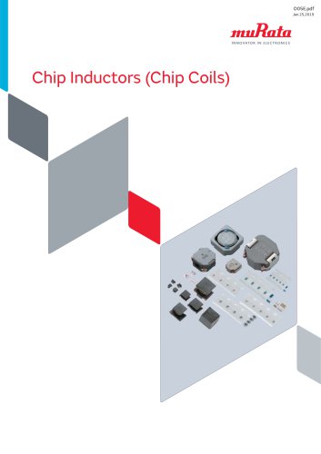 Chip Inductors (Chip Coils)_2019
274 Pages
 Rotary Position Sensors_2013
23 Pages
 Chip Inductors (Chip Coils)_2013
249 Pages
 Pyroelectric Infrared Sensors
22 Pages
 Chip Monolithic Ceramic Capacitors
220 Pages
 Trimmer Potentiometers
59 Pages
 Crystal Resonator
3 Pages
 MURATA PRODUCTS 2010-2011
423 Pages
 NTC/PTC Thermistors for Automotive
71 Pages
 Trimmer Capacitors
44 Pages


