- Catalogs
- Murata Electronics
- High Frequency Single Layer Microchip Capacitors
High Frequency Single Layer Microchip Capacitors
1 /15Pages

High Frequency Single Layer Microchip Capacitors
1 /15Pages
Catalog excerpts

Cat.No.C01E-3 High Frequency Single Layer Microchip Capacitors
Open the catalog to page 1
for EU RoHS Compliant • All the products in this catalog comply with EU RoHS. • EU RoHS is "the European Directive 2002/95/EC on the Restriction of the Use of Certain Hazardous Substances in Electrical and Electronic Equipment". • For more details, please refer to our website 'Murata's Approach for EU RoHS' (http://www.murata.com/info/rohs.html).
Open the catalog to page 2
Part Numbering 2 High Frequency Single Layer Microchip Capacitors 3 Temperature Compensating 5C Characteristics (0±30ppm/°C) 4 Temperature Compensating 6U Characteristics (-750±60ppm/°C) 5 Temperature Compensating 7K Characteristics (-2200±500ppm/°C) 6 High Dielectric B5 Characteristics (±10%) 7 High Dielectric F9 Characteristics (+30%, -80%) 8 High Dielectric W1 Characteristics (+30%, -90%) 9 Multi-plate Type 9 Specifications and Test Methods 10 Notice 12
Open the catalog to page 3
2 (Part Number) qProduct ID wSeries CL High Frequency Microchip Capacitors -25 to 85°C -25 to 85°C -25 to 85°C -25 to 85°C -25 to 85°C -25 to 85°C 0±30ppm/°C -750±60ppm/°C -2200±500ppm/°C ±10% +30,-80% +30,-90% Product ID rTemperature Characteristics 5C 6U 7K B5 F9 W1 Code Temperature Range Capacitance Change tCapacitance Expressed by three figures. The unit is pico-farad (pF). The first and second figures are significant digits, and the third figure expresses the number of zeros which follow the two numbers. If there is a decimal point, it is expressed by the capital letter "R". In this case,...
Open the catalog to page 4
High Frequency Single Layer Microchip Capacitors n Features 1. Fine grained high-density ceramic dielectric, pure gold electrode and simple single layer structure provide very reliable performance and excellent frequency characteristics. 2. A wide selection of sizes from very miniature 0.25mm square is suited to high-density mounting. 3. For compatibility with the gold electrodes, die bonding with Au-Sn is possible and wire bonding with gold wire is possible. 4. To improve handling of bonding, Au-Sn coating is available on one side or both sides. 5. Custom made type (dimensions, cap. values,...
Open the catalog to page 5
4 Size Code L WT (max.) Capacitance and Tolerance 0A 0.25 0.25 0.35 0C 0.35 0.25 0.35 0D 0.38 0.38 0.35 05 0.50 0.50 0.35 0E 0.55 0.38 0.35 0F 0.64 0.64 0.35 0G 0.70 0.50 0.35 0H 0.71 0.38 0.35 0J 0.76 0.76 0.35 09 0.90 0.90 0.35 1A 1.00 0.64 0.35 1B 1.09 0.76 0.35 1C 1.27 1.27 0.35 1E 1.49 0.90 0.35 1G 1.73 1.27 0.35 1H 1.78 1.78 0.45 2C 2.19 1.27 0.45 2E 2.29 2.29 0.45 2L 2.95 1.78 0.45 0.1pF (0R1) B 0.2pF (0R2) B B 0.3pF (0R3) B B B 0.4pF (0R4) B B B B 0.5pF (0R5) B B B B B 0.6pF (0R6) B B B B B 0.7pF (0R7) B B B B B 0.8pF (0R8) B B B B B 0.9pF (0R9) B B B B 1.0pF (1R0) K K K K K 1.1pF (1R1)...
Open the catalog to page 6
Size Code L WT (max.) Capacitance and Tolerance 0A 0.25 0.25 0.35 0B 0.30 0.25 0.35 0C 0.35 0.25 0.35 0D 0.38 0.38 0.35 05 0.50 0.50 0.35 0E 0.55 0.38 0.35 0F 0.64 0.64 0.35 0G 0.70 0.50 0.35 0H 0.71 0.38 0.35 0J 0.76 0.76 0.35 09 0.90 0.90 0.35 1A 1.00 0.64 0.35 1C 1.27 1.27 0.35 1E 1.49 0.90 0.35 1G 1.73 1.27 0.35 1H 1.78 1.78 0.45 2.0pF (2R0) K 2.2pF (2R2) K 2.4pF (2R4) K 2.7pF (2R7) K 3.0pF (3R0) K 3.3pF (3R3) K 3.6pF (3R6) K 3.9pF (3R9) K 4.3pF (4R3) K 4.7pF (4R7) K 5.1pF (5R1) K K 5.6pF (5R6) K K K 6.2pF (6R2) K K K 6.8pF (6R8) K K K 7.5pF (7R5) K K K 8.2pF (8R2) K K K 9.1pF (9R1) K K K...
Open the catalog to page 9
8 Capacitance and Tolerance 270pF (271) K 300pF (301) K K 330pF (331) K 360pF (361) K 390pF (391) K 430pF (431) K 470pF (471) 510pF (511) 560pF (561) 620pF (621) Custom capacitors (dimensions, capacitance, etc.) are available upon request. Please consult us for details. The digits shown in ( ) following capacitance are part numbering codes. Dimensions are shown in mm. Capacitance Tolerance K: ±10% High Dielectric F9 Characteristics (+30%, -80%) Part Number Size Code L WT (max.) Capacitance and Tolerance 0A 0.25 0.25 0.35 0B 0.30 0.25 0.35 0C 0.35 0.25 0.35 0D 0.38 0.38 0.35 05 0.50 0.50 0.35...
Open the catalog to page 10
Size Code L WT (max.) Capacitance and Tolerance 0A 0.25 0.25 0.35 0D 0.38 0.38 0.35 05 0.50 0.50 0.35 0F 0.64 0.64 0.35 0J 0.76 0.76 0.35 09 0.90 0.90 0.35 36pF (360) Z 39pF (390) Z 43pF (430) Z 47pF (470) Z 51pF (510) Z 56pF (560) Z 91pF (910) Z 100pF (101) Z 110pF (111) Z 120pF (121) Z 130pF (131) Z Z 150pF (151) Z Z 160pF (161) Z 180pF (181) Z 200pF (201) Z 220pF (221) Z Z 240pF (241) Z 270pF (271) Z 300pF (301) Z 330pF (331) Z Z 360pF (361) Z Z 390pF (391) Z Z Z 430pF (431) Z Z 470pF (471) Z Z 510pF (511) Z Z 560pF (561) Z Z 620pF (621) Z 680pF (681) Z Custom capacitors (dimensions, capacitance,...
Open the catalog to page 11
Continued on the following page. MIL-STD-202 Method 103 1000±12 hours at 60±5°C in 90 to 95% relative humidity 12 Humidity (No Load) Appearance No mechanical damage Capacitance Change 5C, 6U, 7K: V±5% or V±0.5pF (whichever is greater) B5, F9, W1: V±10% Q/D. F. 5C, 6U: QU100 7K: QU80 B5, F9: D. F.V2.5% W1: D. F.V4% I. R. U30% of initial requirement D. W. V. No damage MIL-STD-202 Method 107Condition A-1 Note : Temperature in step 3 is +125W Y 30 °C and time for steps 1 and 3 is 30 minutes. 11 Thermal Shock Appearance No mechanical damage Capacitance Change 5C, 6U, 7K: V±5% or V±0.5pF (whichever...
Open the catalog to page 12
240 hours at 85±2°C in 85±5% relative humidity with applied bias voltage of 1.5Vdc±10% 14 Humidity Load Appearance No mechanical damage Capacitance Change 5C, 6U, 7K: V±5% or V±0.5pF (whichever is greater) B5, F9, W1: V±10% Q/D. F. 5C, 6U: QU100 7K: QU50 B5, F9: D. F.V2.5% W1: D. F.V4% I. R. U10000M½ D. W. V. No damage MIL-STD-202 Method 108 1000±12 hours at 125±3°C with 200% of the rated voltage applied 13 High Temperature Load Appearance No mechanical damage Capacitance Change 5C, 6U, 7K: V±5% or V±0.5pF (whichever is greater) B5, F9, W1: V±10% Q/D. F. 5C, 6U: QU100 7K: QU80 B5, F9: D. F.V2.5%...
Open the catalog to page 13
12 n Notice (Soldering and Mounting) Note the following to prevent poor die bonding and poor wire bonding. 1. Store the capacitors in manufacturer's package in the following conditions without a rapid thermal change in an indoor room. •Temperature: -10 to 40 degree C •Humidity: 30 to 70%RH 2. Avoid storing the capacitors in the following conditions. (a) Ambient air containing corrosive gas. (Chlorine gas, Hydrogen sulfide gas, Ammonia gas, Sulfuric acid gas, Nitric oxide gas, etc.) (b) Ambient air containing volatile or combustible gas (c) In environments with a high concentration of airborne...
Open the catalog to page 14All Murata Electronics catalogs and technical brochures
 High Voltage Resistors
2 Pages
 XMSSJE3G0PA-003
5 Pages
 MURATA PRODUCTS Lineup 2018
164 Pages
 Murata Products for Automotive
13 Pages
 MURATA PRODUCTS Lineup
150 Pages
 MURATA PRODUCTS Lineup
136 Pages
 Ceramic Resonators "CERALOCK®"
46 Pages
 Piezoelectric Sound Components
28 Pages
 Chip Monolithic Ceramic Capacitors
182 Pages
 Trimmer Capacitors
39 Pages
 MEMS Sensors
4 Pages
 Ceramic Resonators CERALOCK®
32 Pages
 EMI Suppression Filters for AC
27 Pages
 Magnetic Switch
3 Pages
 Chip Multilayer LC Filters
9 Pages
 SAW Traps
1 Page


Archived catalogs
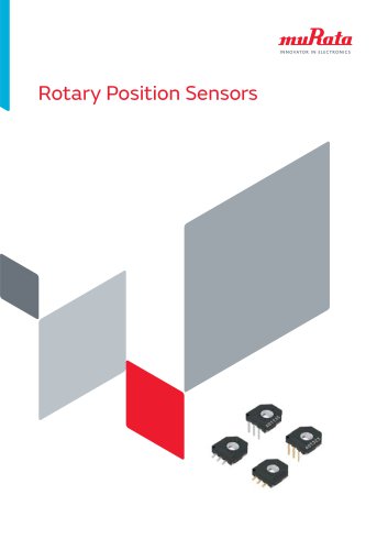 Rotary Position Sensors_2015
26 Pages
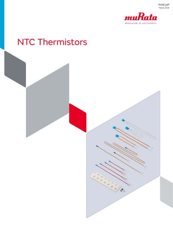 NTC Thermistors_2020
37 Pages
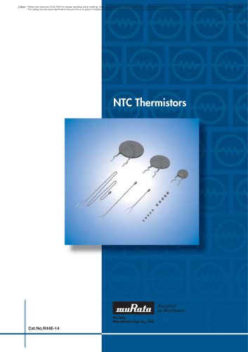 NTC Thermistors_2012
40 Pages
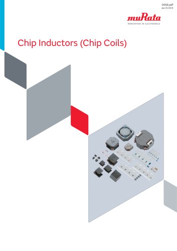 Chip Inductors (Chip Coils)_2019
274 Pages
 Rotary Position Sensors_2013
23 Pages
 Chip Inductors (Chip Coils)_2013
249 Pages
 Pyroelectric Infrared Sensors
22 Pages
 Chip Monolithic Ceramic Capacitors
220 Pages
 Trimmer Potentiometers
59 Pages
 Crystal Resonator
3 Pages
 MURATA PRODUCTS 2010-2011
423 Pages
 NTC/PTC Thermistors for Automotive
71 Pages
 Trimmer Capacitors
44 Pages


- Connector
- Transformer
- Dry transformer
- Digital indicator
- Air blower
- DC-DC converter
- Centrifugal blower
- Encapsulated transformer
- Electronic filter
- Power transformer
- RF connector
- Radio antenna
- Passive electronic filter
- Coaxial connector
- Murata ceramic capacitor
- Rectangular battery
- Murata SMD capacitor
- SMD DC-DC converter
- Cylindrical battery