Low Cost Motor Protection for PWM Drive Applications

Low Cost Motor Protection for PWM Drive Applications
Motor protection filters are cost-effective solutions for enhancing the reliability of inverter-fed motors, extending their lifespan, and addressing over voltage issues due to long leads. This document discusses various motor protection filters, including sine wave and single element low-pass filters, and presents output voltage waveforms and cost data.
1. Introduction
PWM inverters provide motors with nearly sinusoidal current waveforms, but their output voltage can lead to over voltage and insulation fatigue failures. An example is given where a motor connected to an inverter with a 6 KHz switching frequency and 750 ft. distance experiences a peak voltage of 1460V due to reflected waves.
2. Motor Ratings
Standard 460V NEMA Design “B” motors are rated for peak voltages of 1000 volts and dv/dt less than 500 volts per microsecond. Inverter Duty motors can handle up to 1600 volts and dv/dt of 16,000 volts per microsecond. However, motor failures indicate a need for protection filters.
3. Long Leads
Long distances between motors and inverters cause conductors to act as transmission lines, leading to voltage doubling at the motor. Reflection coefficients vary with motor size, with smaller motors experiencing higher coefficients.
4. Critical Cable Length
The critical cable length is the maximum length at which voltage amplification does not occur. It depends on the propagation speed and rise time of the PWM wave front. Table 2 provides critical lengths for various rise times.
5. Long Lead Filter Options
Four options for protecting motors with long leads include:
- Terminator: Matches load impedance with line impedance but requires placement at the motor.
- Dual Element Low-Pass Sine Wave Filter: Converts inverter output to a nearly sinusoidal waveform, allowing unlimited cable length.
- Single Element Low-Pass Filter: Uses a 5% load reactor, reducing peak voltage for lead lengths up to 850 feet.
- High-Frequency Snubber: Consists of a 3% reactor and bypass resistor, with unlimited lead lengths but limited switching frequency.
Catalog excerpts
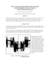
Karl M. Hink, Executive Vice President Originally presented at the Power Quality 99 Conference ABSTRACT Motor protection filters are proven economical devices to improve inverter-fed motor reliability, increase motor life, and solve long lead over voltage problems. This paper demonstrates the benefits and applications of a number of different types of motor protection filters, including sine wave and single element low-pass filters. Output voltage waveforms are presented along with relative cost data. Contemporary pulse width modulated (PWM) inverters provide motors with a nearly sinusoidal current waveform, but their output voltage waveform can cause over voltage failures and fatigue failures in motor electrical insulation systems. Figure 1, for example, shows the typical motor voltage waveform for a drive operating from an inverter with a switching frequency of 6 KHz and a fundamental frequency of 60 Hz. The distance between the inverter and the motor is 750 ft. with 480V input voltage. Peak motor terminal voltage is 1460V. In this example, the conductors connecting the motor to the inverter act as a transmission line, and a voltage doubling is occurring at the motor because of a reflected wave. In addition to over voltage, notice that the motor is being subjected to fast dv/dt pulses. The number of these pulses the motor sees is determined by the switching frequency of the inverter. The faster the switching frequency, the more repetitive pulses the motor will see. It is these pulses which, accumulated over time, can lead to motor insulation system fatigue failures. 1. INTRODUCTION Figure 1. Typical Motor Voltage Waveform 2. MOTOR RATINGS >
Open the catalog to page 1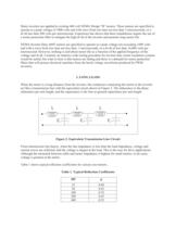
Many inverters are applied to existing 460 volt NEMA Design BӔ motors. These motors are specified to operate at a peak voltage of 1000 volts and with wave front rise time not less than 2 microseconds, or a dv/dt less than 500 volts per microsecond. Experience has shown that these installations require the use of a motor protection filter to mitigate the high dv/dt of the inverter and promote long motor life. NEMA Inverter Duty 460V motors are specified to operate at a peak voltage not exceeding 1600 volts and with a wave front rise time not less than .1 microseconds, or a dv/dt of less than 16,000...
Open the catalog to page 2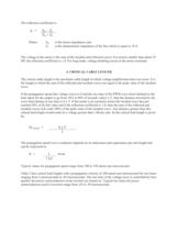
c Where Z > m is the motor impedance, and Z > c is the characteristic impedance of the line which is equal to ֢Ț L/C. The voltage at the motor is the sum of the incident and reflected waves. For motors smaller than about 25 HP, the reflection coefficient is 1.0. For long leads, voltage doubling occurs at the motor terminals. 4. CRITICAL CABLE LENGTH The critical cable length is the maximum cable length at which voltage amplification does not occur. It is the length at which the sum of the reflected and incident waves are equal to the peak value of the incident wave. If the propagation speed (the...
Open the catalog to page 3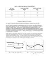
Table 2. Critical Lead Length for Various Rise Times Rise Time (microseconds) Critical Lead Length (meters) Critical Lead Length (feet) 2.00 100 328 1.0 50 164 0.50 25 82 0.10 5 16 0.05 2.5 8 5. LONG LEAD FILTER OPTIONS Four options are generally used for protecting inverter feed motors that operate from long leads. The first is known as a terminator. From transmission line theory, we know that if the load impedance matches the line impedance, then there is no reflected wave. The concept of the terminator is to place an impedance in parallel with the motor where the parallel combination is designed...
Open the catalog to page 4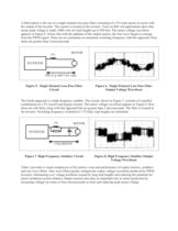
A third option is the use of a single element low-pass filter consisting of a 5% load reactor in series with the output of the inverter. The reactor is located at the inverter. Tests on 460 volt applications show that motor peak voltage is under 1000 volts for lead lengths up to 850 feet. The motor voltage waveform appears in Figure 6. Notice that with the addition of the output reactor, the sine wave begins to emerge from the PWM signal. There are no constraints on minimum switching frequency with this approach. Rise times are greater than 4 microseconds. 5% MOTOR850 ft @ 460 VAC max INVERTER...
Open the catalog to page 5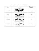
Table 3. Long Lead Filters Performance and Cost Comparison Option Waveform Relative Cost (5HP/460V) Do Nothing 0 Snubber 1.48 5% Reactor 0.65 Sine Wave Filter 1.00 >
Open the catalog to page 6All MTE catalogs and technical brochures
 Noise Suppression Network
2 Pages
 Guard-AC? PLUS
2 Pages
 RFI and EMI Filters
2 Pages
 Matrix PureSine ®
2 Pages
 RL Line/Load Reactors
2 Pages
 RLW Reactors
2 Pages

Archived catalogs
 Motor Protection Filters
2 Pages
 Harmonic Filters
4 Pages
 RFI / EMI Filter Tutorial
17 Pages
 Line Reactor Tutorial
15 Pages
 Load Reactor Tutorial
13 Pages
 Motor Protection Filter Tutorial
11 Pages
 Harmonic Filter Tutorial
36 Pages
 Matrix Filters®
2 Pages
 DC Link Chokes
2 Pages
 MTE Corporation - Catalog
9 Pages


