Harmonic Mitigation of 12-Pulse Drives with Unbalanced Input Line Voltages

Harmonic Mitigation of 12-Pulse Drives with Unbalanced Input Line Voltages
Twelve-pulse drives are often used in HVAC applications for their potential to reduce harmonic current distortion. However, under real-world conditions with unbalanced input line voltages, these drives may not meet IEEE-519 standards. This paper compares the performance of twelve-pulse and six-pulse drives, highlighting the superior harmonic mitigation of a six-pulse drive with a Matrix Harmonic Filter.
Historically, twelve-pulse drives were a cost-effective solution for higher current ratings. They use two six-pulse rectifiers with a 30-degree phase shift achieved through a transformer. The theoretical harmonic components for a twelve-pulse system are at multiples of 11, 13, 23, etc., missing the 5th and 7th harmonics present in six-pulse systems.
The effectiveness of twelve-pulse drives depends on equal current sharing between rectifiers, which is difficult due to transformer impedance differences. A series connection of rectifiers can avoid these issues, simplifying implementation.
Voltage unbalance, common in industrial systems, affects harmonic performance. ANSI C84.1 defines voltage unbalance and suggests most systems operate within 0-3% unbalance. Twelve-pulse drives show significant performance degradation with unbalance, with THID increasing from 12% to 65% as unbalance rises.
Testing shows that a six-pulse drive with a Matrix Harmonic Filter outperforms a twelve-pulse drive under unbalanced conditions. The filter reduces THID significantly, maintaining better performance across load ranges and voltage unbalances.
For HVAC applications with variable loads and voltage unbalances, a six-pulse drive with a Matrix Harmonic Filter offers superior harmonic mitigation compared to a twelve-pulse drive.
Catalog excerpts

HARMONIC MITIGATION OF 12-PULSE DRIVES WITH UNBALANCED INPUT LINE VOLTAGES Karl M. Hink MTE Corporation W147 N 9525 Held Drive Menomonee Falls, WI 53051 Telephone 262-253-8200; Fax 262-253-8210; E-mail: [email protected] ABSTRACT Twelve-pulse drives are frequently specified by consulting engineers for heating, ventilating and air conditioning applications because of their theoretical ability to reduce harmonic current distortion, but very little information has been published showing how twelve-pulse drives perform under actual operating conditions with unbalanced input line voltages. This paper presents test data which demonstrate that twelve-pulse drives do not achieve the level of harmonic mitigation most engineers expect and that these drives may not meet the requirements of IEEE-519 under practical operating conditions. The actual performance of twelve-pulse and six-pulse drives is compared to the performance of a six-pulse drive fed by a Matrix Harmonic Filter. The Matrix Harmonic Filter provides superior harmonic mitigation at lower cost. In the mid 1960s when power semiconductors were only available in limited ratings, twelve-pulse drives provided a simpler and more cost effective approach to achieving higher current ratings than direct paralleling of power semiconductors. This technique is still employed today in very large drive applications. A typical diagram of a large twelve-pulse drive appears in figure 1. The drives input circuit consists of two six-pulse rectifiers, displaced by 30 electrical degrees, operating in parallel. The 30-degree phase shift is obtained by using a phase shifting transformer. The circuit in figure 1 simply uses an isolation transformer with a delta primary, a delta connected secondary, and a second wye connected secondary to obtain the necessary phase shift. Because the instantaneous outputs of each rectifier are not equal, an interphase reactor is used to support the difference in instantaneous rectifier output voltages and permit each rectifier to operate independently. The primary current in the transformer is the sum of each six-pulse rectifier or a twelve-pulse wave form. Theoretical input current harmonics for rectifier circuits are a function of pulse number and can be expressed as: h = (np + 1) where n= 1, 2, 3,҅ and p = pulse number For a six-pulse rectifier, the input current will have harmonic components at the following multiples of the fundamental frequency. 5, 7, 11, 13, 17, 19, 23, 25, 29, 31, etc. For the twelve-pulse system shown in figure 1, the input current will have theoretical harmonic components at the following multiples of the fundamental frequency: 11, 13, 23, 25, 35, 37, etc. . > Page 1 of 1 size="-1">
Open the catalog to page 1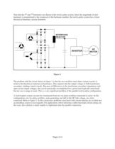
Note that the 5 > th and 7 > th harmonics are absent in the twelve-pulse system. Since the magnitude of each harmonic is proportional to the reciprocal of the harmonic number, the twelve-pulse system has a lower theoretical harmonic current distortion. > INTERPHASE REACTOR INVERTER ACMOTOR Figure 1 The problem with the circuit shown in figure 1 is that the two rectifiers must share current exactly to achieve the theoretical reduction in harmonics. This requires that the output voltage of both transformer secondary windings match exactly. Because of differences in the transformer secondary impedances...
Open the catalog to page 2
Figure 2 A CMOTOR INVERTER Using the series rectifier connection, it is very easy to construct a twelve-pulse drive from a standard six-pulse drive if the six-pulse drive has its DC bus terminals available or permits access to one side of the DC bus. Many standard AC drives provide terminals in the DC bus to accommodate an external DC link choke. These same terminals can be used to add an external rectifier converting the drive to twelve-pulse operation. Refer to figure 3. In this case there is no need for extra circuitry to control inrush current for the second rectifier. The net result is a...
Open the catalog to page 3
Figure 3 INVERTER A CMOTOR To determine how a twelve-pulse drive system operates under unbalanced line voltage conditions, we constructed a 30 HP twelve-pulse drive from a standard delta delta-wye isolation transformer and standard six-pulse drive using the series bridge connection shown in figure 3. An auto transformer could have been used in place of the isolation transformer. The auto transformer costs less and requires less mounting space, but the isolation transformer was selected because it provides better performance and is readily available from stock. The system was tested with line...
Open the catalog to page 4All MTE catalogs and technical brochures
 Noise Suppression Network
2 Pages
 Guard-AC? PLUS
2 Pages
 RFI and EMI Filters
2 Pages
 Matrix PureSine ®
2 Pages
 RL Line/Load Reactors
2 Pages
 RLW Reactors
2 Pages

Archived catalogs
 Motor Protection Filters
2 Pages
 Harmonic Filters
4 Pages
 RFI / EMI Filter Tutorial
17 Pages
 Line Reactor Tutorial
15 Pages
 Load Reactor Tutorial
13 Pages
 Motor Protection Filter Tutorial
11 Pages
 Harmonic Filter Tutorial
36 Pages
 Matrix Filters®
2 Pages
 DC Link Chokes
2 Pages
 MTE Corporation - Catalog
9 Pages


