18-Pulse Drives and Voltage Unbalance

18-Pulse Drives and Voltage Unbalance
This document discusses the performance of eighteen-pulse drives in HVAC applications, particularly under unbalanced input line voltages. It highlights that these drives often do not meet IEEE-519 standards under practical conditions and compares their performance with six-pulse drives using a Matrix Harmonic Filter, which offers better harmonic mitigation at a lower cost.
Introduction
Eighteen-pulse drives were initially developed to achieve higher current ratings and have become popular for harmonic mitigation. They can be constructed in series or parallel configurations, with the series configuration being simpler for harmonic mitigation purposes.
Theoretical Harmonics
The input current harmonics for rectifier circuits depend on the pulse number. For six-pulse rectifiers, harmonics appear at multiples like 5, 7, 11, etc., while eighteen-pulse systems theoretically eliminate lower harmonics like the 5th and 7th, resulting in lower harmonic distortion.
Practical Considerations
Real-world power systems often experience voltage unbalance, affecting the performance of eighteen-pulse drives. ANSI C84.1 defines voltage unbalance and suggests most systems operate within a 0-3% unbalance range.
Testing and Results
A 30 HP eighteen-pulse drive was tested under various conditions. Results showed significant degradation in harmonic performance with increased voltage unbalance and decreased load. Adding line reactors improved performance but still required careful consideration of practical conditions.
Comparison with Matrix Harmonic Filter
The Matrix Harmonic Filter, used with a six-pulse drive, demonstrated superior performance under similar conditions, showing less sensitivity to voltage unbalance and better harmonic mitigation.
Conclusion
For HVAC applications with variable loads and voltage unbalance, a six-pulse drive with a Matrix Harmonic Filter provides better harmonic performance than an eighteen-pulse drive. This solution is more effective in achieving energy efficiency and comfort in variable load conditions.
Catalog excerpts

Karl M. Hink MTE Corporation W147 N 9525 Held Drive Menomonee Falls, WI 53051 Telephone 262-253-8200; Fax 262-253-8210; E-mail: [email protected] ABSTRACT Eighteen-pulse drives are frequently specified by consulting engineers for heating, ventilating and air conditioning applications because of their theoretical ability to reduce harmonic current distortion, but very little information has been published showing how eighteen-pulse drives perform under actual operating conditions with unbalanced input line voltages. This paper presents test data which demonstrate that eighteen-pulse drives do not achieve the level of harmonic mitigation most engineers expect and that these drives may not meet the requirements of IEEE-519 under practical operating conditions. The actual performance of eighteen-pulse and six-pulse drives is compared to the performance of a six-pulse drive fed by a Matrix Harmonic Filter. The Matrix Harmonic Filter provides superior harmonic mitigation at lower cost . In the mid 1960s when power semiconductors were only available in limited current ratings, eighteen-pulse drives provided a simpler and more cost effective approach to achieving higher current ratings than direct paralleling of power semiconductors. With this approach a drive could be easily constructed with almost three times the horsepower available from the largest six pulse converter. The technique is still employed today in very large drive applications. In addition eighteen pulse drives have become a popular approach to harmonic mitigation. Eighteen pulse rectifiers can be constructed to operate in parallel or series. In a series configuration, three six-pulse rectifiers, each generating one third of the DC link voltage, are series connected. The series connection avoids, issues associated with current sharing and eliminates the need for an interphase reactor. For applications where harmonic mitigation rather than high current ratings are the objective, this solution is much simpler to implement than the parallel connection. Using the series rectifier connection, it is very easy to construct an eighteen-pulse drive from a standard six-pulse drive if the six-pulse drive has its DC bus terminals available or permits access to one side of the DC bus. Many standard AC drives provide terminals in the DC bus to accommodate an external DC link choke. These same terminals can be used to add two external rectifiers converting the drive to eighteen-pulse operation. The net result is a system solution well within the means of many system integrators. A typical diagram of a series connected eighteen pulse drive constructed from a standard six- pulse drive, two external rectifiers and a conventional 18 pulse isolation transformer appears in figure 1. The drive has terminals available to connect a DC link choke. These terminals are used to connect the two external rectifiers in series with the drives internal rectifier. The eighteen pulse transformer is designed to provide one third the normal input voltage to each of the three rectifiers at a 20 degree phase displacement from each other. The 20-degree phase shift is obtained by phase shifting the transformers secondary windings. The circuit in figure 1 simply uses an isolation transformer with a delta primary, and three delta connected secondary windings, one shifted + 20 degrees, one shifted -20 degrees and one in phase with the primary. Page 1 of 7 >
Open the catalog to page 1
1) where n= 1, 2, 3, and p = pulse number For a six-pulse rectifier, the input current will have harmonic components at the following multiples of the fundamental frequency. 5, 7, 11, 13, 17, 19, 23, 25, 29, 31, 35, 37, 41, 43, 47, 49, 53, 55, etc. For the eighteen-pulse system shown in figure 1, the input current will have theoretical harmonic components at the following multiples of the fundamental frequency: 17, 19, 35, 37, 53, 55, etc. . Note that the 5 th and 7 > th , 11 > th and 13 > th harmonics are absent in the theoretical eighteen-pulse system. Since the magnitude of each harmonic is...
Open the catalog to page 2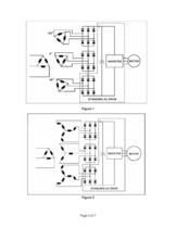
Figure 1 > Figure 2 Page 3 of 7 >
Open the catalog to page 3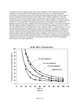
Figure 3 Page 4 of 7 To determine how an eighteen-pulse drive system operates under unbalanced line voltage conditions, we constructed a 30 HP eighteen-pulse drive from a conventional isolation transformer and standard six-pulse drive using the series bridge connection shown in figure 1. An auto transformer could have been used in place of the isolation transformer. The auto transformer costs less and requires less mounting space, but the isolation transformer was selected because it provides better performance and is readily available as a modified standard transformer. Care was taken in the...
Open the catalog to page 4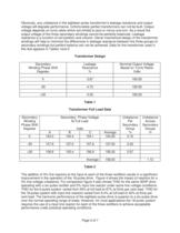
Secondary Winding Phase Shift >
Open the catalog to page 5
Figure 4 > Figure 5 Page 7 of 7 >
Open the catalog to page 7All MTE catalogs and technical brochures
 Noise Suppression Network
2 Pages
 Guard-AC? PLUS
2 Pages
 RFI and EMI Filters
2 Pages
 Matrix PureSine ®
2 Pages
 RL Line/Load Reactors
2 Pages
 RLW Reactors
2 Pages

Archived catalogs
 Motor Protection Filters
2 Pages
 Harmonic Filters
4 Pages
 RFI / EMI Filter Tutorial
17 Pages
 Line Reactor Tutorial
15 Pages
 Load Reactor Tutorial
13 Pages
 Motor Protection Filter Tutorial
11 Pages
 Harmonic Filter Tutorial
36 Pages
 Matrix Filters®
2 Pages
 DC Link Chokes
2 Pages
 MTE Corporation - Catalog
9 Pages


