- Catalogs
- MSC SOFTWARE - HEXAGON MANUFACTURING INTELLIGENCE
- Whitepaper How to Create a Good Quality FE Model
- Company
- Products
- Catalogs
- News & Trends
- Exhibitions
Whitepaper How to Create a Good Quality FE Model
1 /13Pages

Whitepaper How to Create a Good Quality FE Model
1 /13Pages
Catalog excerpts

Whitepaper How to Create a Good Quality FE Model by Cornelia
Open the catalog to page 1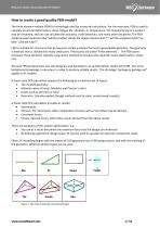
How to create a good quality FEM model? The finite element method (FEM) is increasingly used for structural calculations. For the most part, FEM is used to calculate structural deformation, stress, fatigue life, vibration, or temperature. The manufacturing of a product may be simulated, and one can calculate the acoustics, crash behaviour, and many other disciplines. The FEM model answers questions like "will the product satisfy the design requirements?","will the component fail?" or later "why did it fail?". FEM is suitable for structures that go beyond a simple analytical formula representable geometry. The geometry ...
Open the catalog to page 2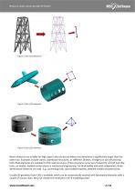
Beam elements are suitable for high aspect ratio structures where one dimension is significantly larger than the other two. Examples include cranes, warehouse structures, or stiffeners (frames, Stringers) in aircraft and ship hulls. Shell elements are suitable for thin wall structures. These structures occur very frequently: aircraft and ship hulls, car bodies, welded constructions in mechanical engineering. For thick walled and solid components, three‐ dimensional elements are used. E.g. connecting rods, cast/molded brackets, detailed models of bolted joints. Usually 3D geometry from CAD is available, which can be automatically meshed with tetrahedral elements with a ...
Open the catalog to page 3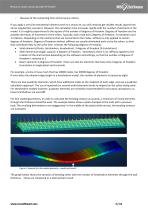
If you apply a very fine tetrahedral element mesh to a structure, you will certainly get reliable results (apart from stress singularities, see later). However, the calculation time increases rapidly with the number of elements in the model. It is roughly proportional to the square of the number of degrees of freedom. Degrees of freedom are the possible directions of movement of the nodes. Typically, each node has 6 degrees of freedom: 3 translations and 3 rotations. Depending on the elements that are connected to the nodes, stiffness is only applied to certain degrees of freedom. Degrees of freedom without stiffness are usually eliminated early on by the solver, so that ...
Open the catalog to page 4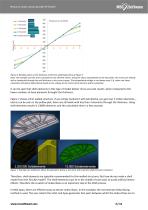
Figure 6: Bending stress on the thickness of the thin‐walled geometry of Figure 5 Note: the example uses the stress calculated in the element Center. Using the stress extrapolated on the key points, the results are already with a hexahedral through the wall thickness in the correct range. The extrapolated voltage is not always used, E.g. when non‐linear calculation the plastic deformation based on the voltage at the center of the element will be evaluated. Therefore, shell elements are typically recommended for thin‐walled structures. But how do you make a shell model from the 3D CAD model? The shell elements must lie in the middle of each wall, to avoid artificial inertia ...
Open the catalog to page 5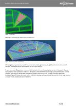
Modeling bar‐shaped structures with beam elements makes good sense, as significantly fewer elements are required and the bar forces and moments can be output directly. If you have a very 3D geometry meshed with tetrahedra, it is worth reducing the number of elements (thereby increasing the solve speed) and improving the quality of the elements by cleaning up the geometry that is to be meshed. MSC Apex can detect and remove short edges, small faces, sliver surfaces, and other geometry problems. Figure 14 shows the mesh before and after cleaning up the geometry. Removal of a short edge leads to ...
Open the catalog to page 7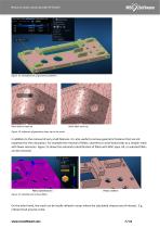
Figure 14: Influence of geometry clean‐up on the mesh In addition to the removal of very small features, it is also useful to remove geometric features that are not important for the calculation. For example the removal of fillets, chamfers or small holes leads to a simpler mesh with fewer elements. Figure 15 shows the automatic identification of fillets with MSC apex. All, or selected fillets can be removed.
Open the catalog to page 8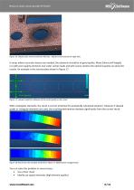
You can solve this problem in several ways: Use a finer mesh Ideally use square elements (high element quality)
Open the catalog to page 9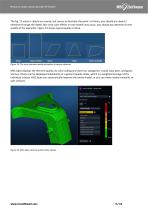
Ideal Aspect Ratio Skew Taper Internal Angle Figure 19: The most common quality deviations in square elements MSC Apex displays the element quality via color coding and uses four categories: invalid, bad, poor, and good. Various criteria can be displayed individually, or a general quality index, which is a weighted average of the individual criteria. MSC Apex can automatically improve the entire model, or you can move nodes manually, or split surfac
Open the catalog to page 10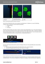
Auto Enhancing of mesh quality Figure 21: Improving the quality of the elements in MSC apex Once we have created the mesh, and can make the remaining entries. In addition to a mesh, the following minimum input is required for a linear static FEA calculation: Material values Loads Restraints MSC Apex indicates whether the model is ready for solving using red/yellow/green icons in the Analysis Readiness panel. Green means that all the necessary inputs are done, and the model is solver‐ready. A yellow icon indicates that the model should be checked – for example, there may be poor quality elements. If red, the model cannot be ...
Open the catalog to page 11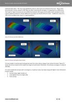
Medium mesh Fine mesh Figure 25: Stresses with highly refined meshes For new models it may be worth testing how much the stress values change if one refines the mesh. Figure 25 shows the stress results for the model from Figure 24 with mesh refinement. The stresses converge to a value of 350 MPa. For some models the stresses don’t converge to a maximum value, but keep rising with higher mesh refinement. Causes include: Internal sharp edges (undercut) Load applied only at
Open the catalog to page 12
Figure 27 below shows an example in which the stresses around a hole did not converge. Mesh Size Fig. 27: Example of stress singularities What can you do in such cases? Instead of using stress results, consider force results and draw conclusions about the durability Consider plastic material behaviour Despite the singularity, use the stresses for qualitative design comparisons (maintain a contstant mesh size) Rate the stress according to FKM or similar methods, in which the stress at a defined distance from the edge is evaluated ...
Open the catalog to page 13All MSC SOFTWARE - HEXAGON MANUFACTURING INTELLIGENCE catalogs and technical brochures
 Corporate Presentation
41 Pages
 Annual Report 2022
88 Pages
 Sustainability Report 2022
58 Pages


Archived catalogs
 Simufact Welding
8 Pages
 Sustainability
92 Pages
 CO-SIMULATION
92 Pages
 ODYSSEE (CADLM)
5 Pages
 MaterialCenter Brochure
12 Pages
 Actran
12 Pages
 Adams/Machinery
12 Pages


- Management software solution
- Automation software solution
- Analysis software solution
- Process software
- Real-time software
- Computer-aided design software
- Cloud-based software
- Control software
- Design software solution
- Monitoring software solution
- 3D software solution
- Industrial software
- Interface software
- Measurement software
- Quality software
- Visualization software solution
- Simulation software solution
- Automated software
- Development software
- Network software