
- Catalogs
- MS Resistances
- Neutral grounding resistors

Neutral grounding resistors

Neutral grounding resistors
The document focuses on grounding systems in power networks, emphasizing the importance of transporting energy from power stations to end users. It categorizes networks into Very High Voltage (VHV), High Voltage (HV), Medium Voltage (MV), and Low Voltage (LV). Proper design, operation, and maintenance are crucial to prevent failures due to atmospheric conditions, mechanical issues, and insulation defects.
Four types of faults in three-phase networks are identified: three-phase fault, phase-to-phase fault clear of earth, two-phase to earth fault, and phase-to-earth fault. Short circuits, caused by insulation defects, can be permanent, fugitive, or intermittent, impacting networks, equipment, supply, and telecommunications.
Protection apparatus and components are essential for controlling and measuring voltage frequency and current. Faults are indicated when controlled values fall outside specified ranges.
The purpose of earthing systems is to protect life and property during faults and transient phenomena. Earthing methods include insulated, solid earthing, and impedance earthing, each with specific protection schemes.
Factors influencing the choice of earthing method include voltage level, insulation coordination, and limitation of fault current. Different methods of neutral earthing are discussed, including insulated, solidly earthed, low resistance grounding, high resistance grounding, earthing reactance, and arc suppression coil.
This system does not intentionally earth the neutral, relying on system capacity to earth. It allows operation with present earth faults but makes fault location detection challenging.
The neutral is directly connected to the station ground, allowing fault current to rise significantly. This method does not limit fault current.
This method limits fault current for safety, using resistors, reactance, or arc suppression coils. It is designed to reduce destructive effects and mechanical stresses.
Commonly used when the neutral of the supply transformer is available, this method is efficient and economical, especially with Nickel Chrome stainless steel resistors.
Key parameters include rated voltage, fault current, time, and resistance value. The insulation level must withstand voltage between the resistor's active part and earth.
Formulas for designing high power or high voltage resistors are provided, including Ohm's Law and energy absorption calculations. The document explains adiabatic heating and the calculation of hot resistance value.
Fault current must align with the protection scheme and equipment's nominal current. The selection of resistance material is crucial for maintaining voltage and limiting fault current.
The document discusses the use of different resistance materials for building resistors, focusing on Nickel Chrome AISI 304 and Ohmalloy. It specifies the maximum fault current allowed (1000 A) and the temperature rise (∆θ: 760°C) as per IEEE-32 standards. The voltage value is calculated as 9.6kV.
- Nickel Chrome AISI 304: High temperature coefficient (α = 0.001/°C), resistance increases significantly with temperature.
- Ohmalloy: Lower temperature coefficient (α = 0.00012/°C), resistance increases less with temperature.
- Other materials discussed include Nickel Chromium Stainless Steel, Aluminium Chromium alloy, and Konstantan.
The selection of alloy depends on electrical and mechanical requirements. The material should have a high temperature coefficient, low resistance to scale, and be non-magnetic to limit electromagnetic fields and vibrations.
Various technologies are used to build resistors, including grid type, edgewound coil type, mats type, and liquid type. Liquid resistors require more maintenance and have limitations on fault occurrences.
Ceramic and steatite rings are recommended for insulation to avoid failure due to high temperature and humidity. Mica is not recommended for tropical areas.
Resistors can be air-cooled (natural or forced ventilation), oil-cooled, water-cooled, or gas-cooled. Each type has specific applications and maintenance requirements.
Different protection degrees (IP00, IP23, IP43, IP54) are discussed, with recommendations for indoor and outdoor installations. Hot dip galvanizing is recommended for housing to protect against corrosion.
The document compares materials and technologies used in high voltage neutral grounding resistors, recommending non-magnetic, non-inductive materials with high temperature coefficients.
Provides a template for specifying electrical data, insulation, accessories, arrangement, connections, and environmental considerations for neutral earthing resistors.
Catalog excerpts
MICROELETTRICA SCIENTIFICA M.S. RESISTANCES Grounding.Doc 1/18 GROUNDING SYSTEMS
Open the catalog to page 1
MICROELETTRICA SCIENTIFICA M.S. RESISTANCES Grounding.Doc 2/18 INTRODUCTION NETWORKS In the most industrial countries, the power generation stations are located far from cities and centres of consumption. The generated energy must be transported from the power generation centre and distributed to the end users (industrial or public). There are 4 types of networks Ø Very High Voltage: VHV Ø High Voltage: HV Ø Medium Voltage: MV Ø Low Voltage: LV The networks are designed, properly operated, maintained and kept in repair to prevent and avoid failures due to: Ø atmospheric: surge, storms Ø mechanical...
Open the catalog to page 2
MICROELETTRICA SCIENTIFICA M.S. RESISTANCES Grounding.Doc 3/18 Short circuits have a disastrous effect on: networks, equipments, supplies, telecommunications networks & security. They must be detected, eliminated or reduced: Ø by an adequate protection material and components Ø by an adequate earthing method. ü Networks Near the power generation center, short circuits are able to reduce the resistant torque of generator and upsetting the balance. ü Equipment The over current induced by short circuits can rise up to 20 to 30 times the value of nominal currents. The over current will create a thermal...
Open the catalog to page 3
MICROELETTRICA SCIENTIFICA M.S. RESISTANCES Grounding.Doc 4/18 SYSTEM EARTHING DESIGN CONSIDERATIONS The general purpose of earthing system is to protect life and property in the event of 50/60 Hz faults (short-circuit) and transient phenomena (lightning, switching operations). The question of how a system shall be earthed is governed by the regulation. The choice of earthing to one point on each system is designed to prevent the passage of current through the earth under normal conditions, and thus to avoid the accompanying risks of electrolysis and interference with communication circuits....
Open the catalog to page 4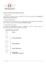
MICROELETTRICA SCIENTIFICA M.S. RESISTANCES Grounding.Doc 5/18 CRITERIA TO CHOOSE THE EARTHING METHOD VOLTAGE LEVEL: The insulation level of material (transformer, generator, etc.) must be in accordance with the induced over voltage at the time of short circuit. INSULATION COORDINATION: The earth fault current will induce locally an over voltage which must be compatible with the insulation of low and medium voltage components, to ensure the continuity of supply. LIMITATION OF FAULT CURRENT To reduce the electrodynamics stresses on material, to limit the induced voltage on telecommunications lines...
Open the catalog to page 5
MICROELETTRICA SCIENTIFICA M.S. RESISTANCES grounding.doc 6/18 Insulated Solidly Earthed Low Resistance Grounding High Resistance Grounding Earthing Reactance Arc Suppression Coil Few Amps 20 To 30 Times From 100 To 3000A Less Than 10A At Least 25 To 60 % 0 Fault Current 3cwv The Value Of Nominal Current Three Phase Fault Current Over voltage Yes No No No No 0 Line To Line Voltage Line To Ground Voltage Line To Ground Voltage Line To Ground Voltage Line To Ground Voltage Double Earth Fault Yes No Slight Slight Slight Yes Earth Fault Arc Self Quenching Sustained Partly Self Quenching Partly Self...
Open the catalog to page 6
MICROELETTRICA SCIENTIFICA M.S. RESISTANCES grounding.doc 7/18 INSULATED NEUTRAL SYSTEM (No Intentional Earthing) The neutral is not earthed directly. In reality, the electrical system is earthed through the system capacity to earth. The earth fault causes a few amperes fault current due to the cable capacitance current, and the voltage of healthy phases will not rise above the line to line voltage. So, the system can operate with present earth fault improving the system continuity and supply. The detection of fault location is very difficult. The main detection components is a voltmeter. This...
Open the catalog to page 7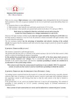
MICROELETTRICA SCIENTIFICA M.S. RESISTANCES grounding.doc 8/18 There are two classes, High resistance value or low resistance value, distinguished by the level of ground fault permitted to flow (No recognized standards for the level of earth fault current that defines these two classes). Ø In practice there is a clear difference. Ø High resistance value typically uses earth fault current levels of 10 A or less. Ø Low resistance value typically uses ground fault current levels above 10 A and up to 3000 A . Both classes are designed to limit the earth fault current and to keep the system free from...
Open the catalog to page 8
MICROELETTRICA SCIENTIFICA M.S. RESISTANCES grounding.doc 9/18 OBTAINING THE SYSTEM NEUTRAL The best way to obtain the system neutral for grounding purposes in three phases systems is to use source transformers or generators with Wye-connected windings. The neutral is the readily available. When the system neutral may not available, earthing transformer may be used to obtain the neutral. EARTHING THROUGH RESISTORS This is the most common solution. It is used when the neutral of the supply transformer is available (DELTA/WYE) and its own impedance is not enough to limit fault current. Experience...
Open the catalog to page 9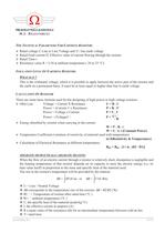
MICROELETTRICA SCIENTIFICA M.S. RESISTANCES grounding.doc 10/18 THE TECHNICAL PARAMETERS FOR EARTHING RESISTOR: Ø Rated voltage U Line to Line Voltage and V= line earth voltage Ø Rated Fault current If, Effective value of current flowing through the resistor. Ø Rated Time t Ø Resistance value R = U/If at ambient temperature ( 20 or 25 °C). INSULATION LEVEL OF EARTHING RESISTOR: WHAT IS IT ? This is the withstand voltage, which it is possible to apply between the active part of the resistor and the earth on a permanent basis. It must be at least equal or higher than line to earth voltage CALCULATION...
Open the catalog to page 10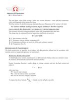
MICROELETTRICA SCIENTIFICA M.S. RESISTANCES grounding.doc 11/18 The real ohmic value of the resistor is taken into account, because it varies with the temperature which itself depends on the current flow time. With that method of calculation we can determine the exact dimensions of the resistor to be built. For resistors adiabatic heating, masses as high as possible are therefore required. CALCULATION OF HOT RESISTANCE VALUE (RESISTANCE VALUE AFTER RATED TIME): The resistance of resistor element changes to extent with temperature after rated time The change may be calculated from the temperature...
Open the catalog to page 11All MS Resistances catalogs and technical brochures
 Single Pole Outdoor Type
4 Pages
 Single Pole Indoor Type
2 Pages
 Voltage transformers
11 Pages
 Load Banks
2 Pages
 Neutral Grounding resistors
4 Pages
 Damping Resistors
24 Pages



- Dry transformer
- Isolator switch
- Current transformer
- Encapsulated transformer
- Low-voltage transformer
- Instrument transformer
- Wire-wound resistor
- 3-pole switch disconnector
- Toroidal transformer
- Through-hole transformer
- Load bank
- Housed resistor
- Outdoor isolator switch
- High-voltage isolator switch
- Single-pole isolator switch
- Medium-voltage switch disconnector
- Aluminum-housed resistor
- Floor-standing resistor
- Ground fault resistor