Catalog excerpts
MIICROEELLEETTTTRIICA SSCIIEENTTIIFFIICA M..SS.. REESSIISSTTANCEESS Created by ElassadD:\suivi clients\Word\Resistors\HARMONIC FILTER.doc PAGE 1/9 HARMONIC PHENOMENON IN INDUSTRIAL POWER SYSTEMS & DAMPING RESISTORS
Open the catalog to page 1
MIICROEELLEETTTTRIICA SSCIIEENTTIIFFIICA M..SS.. REESSIISSTTANCEESS Created by ElassadD:\suivi clients\Word\Resistors\HARMONIC FILTER.doc PAGE 2/9 HARMONIC IN INDUSTRIAL POWER SYSTEMS The level of harmonic voltages and currents in electrical power systems are increasing . The principle cause is the proliferation of devices which produce harmonics ( mainly static converters , variable speed drives , traction systems etc.) The single largest cause of severe harmonic distortion is resonance. A “normal “harmonic can be amplified by about 10 to 25 times if resonance occurs at or close to...
Open the catalog to page 2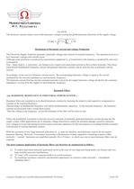
MIICROEELLEETTTTRIICA SSCIIEENTTIIFFIICA M..SS.. REESSIISSTTANCEESS Created by ElassadD:\suivi clients\Word\Resistors\HARMONIC FILTER.doc PAGE 3/9 Uh=Zh*Ih The harmonic currents induce most of the harmonic voltages causing the global harmonic distortion of the supply voltage å = = + n h Urms U U h 2 ²1 ² Mechanism of Harmonic current and voltage Production The Electricity Supply Authority generates sinusoidal voltages and currents at nominal frequency . The question arises as to how harmonic voltages and currents occur Although some distortion is produced by transmission equipment (e. g...
Open the catalog to page 3
MIICROEELLEETTTTRIICA SSCIIEENTTIIFFIICA M..SS.. REESSIISSTTANCEESS Created by ElassadD:\suivi clients\Word\Resistors\HARMONIC FILTER.doc PAGE 4/9 DAMPING RESISTORS IN HARMONIC FILTERS In order to control the impedance in a electrical system with harmonic current generation filter circuits are used. They allow to fix a low impedance at defined fixed frequency independent of the network. In order to build such filters the traditional electro technical offers the use of capacitors and inductors. By connecting this two elements in various configuration a well defined frequency response can be...
Open the catalog to page 4
MIICROEELLEETTTTRIICA SSCIIEENTTIIFFIICA M..SS.. REESSIISSTTANCEESS Created by ElassadD:\suivi clients\Word\Resistors\HARMONIC FILTER.doc PAGE 5/9 Time Temperature qT q2 q1 T B A C t = f(q) A=Tolerance of resistance value at operating stage B=Tolerance of resistance value at ambient temperature C =Tolerance of resistance value from cold to hot stage q1 =Ambient temperature ,qT =63.2%of q2 q2 =maximum temperature T = Time constant By calculation and simulation tests results and data, A, B & C can be obtained easily. Taps on Resistor The resistance value of resistor cannot be adjusted easily...
Open the catalog to page 5
MIICROEELLEETTTTRIICA SSCIIEENTTIIFFIICA M..SS.. REESSIISSTTANCEESS Created by ElassadD:\suivi clients\Word\Resistors\HARMONIC FILTER.doc PAGE 6/9 Load, over-load & Energy pulse The damping Resistor as other components of Harmonic Filter (capacitors, reactor) must withstand the same stress in terms of voltage, current and environment conditions with a thermal stress in addition due to energy dissipation. This energizing is a combination of a permanent current Irms W = ò ¥ 0 R Irms 2 x dt = m c Dq Irms = I I In 1 2 2 + 2 + 2 From time to time an additional overload as result of a temporary...
Open the catalog to page 6
MIICROEELLEETTTTRIICA SSCIIEENTTIIFFIICA M..SS.. REESSIISSTTANCEESS Created by ElassadD:\suivi clients\Word\Resistors\HARMONIC FILTER.doc PAGE 7/9 COMPARISON Protection degree Protection Comments IP00 No protection Suitable for indoor installation IP23 Protected against solid objects greater than 12 mm and against spraying water. - Suitable and recommended for indoor or outdoor installation ,cooling time is approximately 10 to 30 the heating time . IP43 Protected against solid objects greater than 1 mm and against spaying water. - Suitable for outdoor installation. The cooling time is...
Open the catalog to page 7
MIICROEELLEETTTTRIICA SSCIIEENTTIIFFIICA M..SS.. REESSIISSTTANCEESS Created by ElassadD:\suivi clients\Word\Resistors\HARMONIC FILTER.doc PAGE 8/9 CLEARANCE For voltage range I: 1 kV < Um < 52 kV Non-reduced values Reduced values Nominal Voltage Maximum voltage for apparatus Rated lightning impulse withstand voltage Minimum clearances phase-to-phase phase-to-earth Rated lightning impulse withstand voltage Minimum clearances phase-to-phase phase-to-earth Un kV Um kV UrB kV Indoor N mm Outdoor N mm UrB kV Indoors S mm Outdoor S mm 3 6 10 3.6 7.2 12 40 60 75 60 90 120 120 120 150 20 40 60 60...
Open the catalog to page 8
MIICROEELLEETTTTRIICA SSCIIEENTTIIFFIICA M..SS.. REESSIISSTTANCEESS Created by ElassadD:\suivi clients\Word\Resistors\HARMONIC FILTER.doc PAGE 9/9 DAMPING RESISTORS TECHNICAL DATA SHEET System Voltage KV Resistance value at continuous rating W +- % Inductance / Frequency mH Continuous power kW or A Overload kW or A Time between events Sec INSULATION LEVEL & LIGHTNING IMPULSE WITHSTANDING High Voltage Terminal to Earth kV Across resistor kV Low Voltage Terminal to Earth kV SITE CONDITIONS Wind Speed km/h Seismic conditions Vertical acceleration g Horizontal acceleration g ARRANGEMENT Outdoor...
Open the catalog to page 9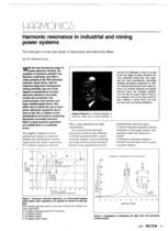
Harmonie rsonance in industrial and mining power Systems The firsl part in a two-part study of harmonies and harmonie fillers By R E. Prelorius Prno W 1U1 th飩 evcfnncrcasmg usage of power electronte devlces, the question ol harmonie pollution has become a real (actor and often a major problcm In the RSA eJectrical scnario. South frlca. wfth rts extensfve deep level underground mining actlvlties, has onc of the hlghest concentrations ol power electronic devices in the workf, mostly due to thyrfstor and cyctoconverter mine winders and large variable-speed drives, Onc etther has to restrict...
Open the catalog to page 10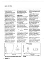
URRMONIGS O Interactive rsonance between consumer syslems which share a por.l of common coup* ng (PCC). The increased application of power capaolors for imptovlng powcr <actor (induding applications (nvoK/ing changeovftr from KW to kVA demand tariff) results in a towering o( the rsonance frequency. as the laNer is mvarsety proporJonal to the square root of total System capacitartce. Figure 1 australes the rela:ionship between sonance frequency and uncorr^ctec S^ower factor for four diff驩rent 'suppiy slrengths', based on the assumption that suffirent capaatance is added to correct the power...
Open the catalog to page 11All MS Resistances catalogs and technical brochures
-
Single Pole Outdoor Type
4 Pages
-
Single Pole Indoor Type
2 Pages
-
Voltage transformers
11 Pages
-
Load Banks
2 Pages
-
Neutral Grounding resistors
4 Pages
-
Neutral grounding resistors
22 Pages


