- Products
- Catalogs
- News & Trends
- Exhibitions
Structural components
1 /78Pages

Structural components
1 /78Pages
Catalog excerpts
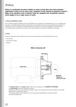
Nois e Noise is a particularly pervasive problem so much so that there have been statutory regulations in place now for some years, designed to limit harmful occupational exposure. Many of the machines used in industry today are equipped with oil-hydraulic systems, which happen to be a major source of noise. 1. Theory and definition of noise From a health and hygiene standpoint, noise can be defined as an unpleasant and undesirable sound, or an unpleasant and annoying or intolerable auditory sensation (noise being any sound phenomena that may be accompanied by sensations of disturbance and pain)....
Open the catalog to page 2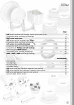
LMC series monobloc bell housings - piston/vane/screw pumps 4 Comparative table, monobloc bell housings 9 BMC series motor base 10 LMC series cast bell housings - gear pumps 14 Comparative table, monobloc bell housings 25 LMS series low noise bell housings 28 Comparative table, low noise bell housings 35 Components for MODUL 2/3 bell housings 36 Bell housings for NEMA motors 44 Comparative table, modular bell housings 50 SGEA - SGEG - SGES series drive couplings 52 LVA series visual level indicators (Inspection door options) 70 LEG series electrical level indicators (Inspection door options)...
Open the catalog to page 3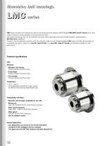
Monobloc bell housings L M C series LMC series monobloc bell housings are used as connecting elements between B3-B5 flanged UNEL-MEC electric motors and a wide range of hydraulic pumps available on the international market. With special machining, they can be modified to serve as motors base that will accept standard flanges manufactured by MP Filtri S.P.A. (MODUL-2). Thanks to their considerable versatility and to the extensive range of pump flanges available, LMC series monobloc bell housings are compatible with electric motors from size 80, rated 0.5 kW, up to size 225, rated 37/45 kW, and...
Open the catalog to page 4
How to use the catalogue This catalogue provides all the technical and dimensional data needed in order to ensure the correct selection of an LMC series bell housing. • Having established the rated power of the electric motor and type of pump that will be adopted to make up the unit, refer to the tables of combinations, locate the correct pairing of motor and pump, and identify the code of the pump flange. • Table 2 presents all the combinations possible between motor base and pump flange. With this information, the customer can determine the exact distance H1 to be bridged by the LMC bell housing...
Open the catalog to page 5
Monobloc bell housing BCD Auxiliary flange Monobloc bell housing Spigot hole H1 (Composite bell housing) The auxiliary flange, if specified, is supplied already fitted to the bell housing (MODUL-2). Machining tolerances • For loose components see pages 11 - 12 - 13 • Check that the pump interface dimensions are compatible with those of the bell housing N.B. The hole made in the tank cover should be 2 mm larger than dimension D5 Concentricity of D1/Spigot hole LMC 200 - LMC 350 LMC 300 - LMC 450 TABLE 1 Dimensions of LMC monobloc bell housing Bell housing code Frame size Foot bracket code To determine...
Open the catalog to page 6
LM C bell housing, dimension H1 TABLE 2 Specified tightening torques for auxiliary flange Monobloc bell housing Code TABLE 3 Modul 2 bell housing Code These values are calculated to exploit the performance of the bolt at 70% of its elastic limit. This means in practice that the shank of the bolt will be stressed typically to 60-70% of its limit of elasticity in the course of being tightened. The values indicated are valid for hexagon head bolts to UNI 5737 and hexagon socket screws to UNI 5931, property class 8.8, tightened by degrees using a torque wrench. If bolts or screws are tightened using...
Open the catalog to page 7
LMC or dering i nfor mation Monobloc bell housing 4 - Pump interface codes Holes rotated through 45°in relation to standard position (page 51) Inspection hole Drain hole + inspection hole Double set of holes Black anodized finish Clearance holes at motor interface Customer specification 450 2 - Product revision code A 3 - Bell housing FSJ Foot bracket N.B. Bell housings with FI/DI options are supplied complete with threaded closure plug 1 - Product revision code A Black anodized finish N.B. For customization features other than those indicated on this page, contact the Technical and Sales Department...
Open the catalog to page 8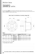
Motors base B M C series The motors base of the BMC series are derived from standard LMC monobloc bell housings, and used as bases to which flanges of the FR/FP5/FP6 series can be fitted either to increase the height of the bell housing or to allow machining of the pump interface, not possible with a standard monobloc housing Motor base for installation of auxiliar y flange FR1 H1 28° TABLE 4 Electric motor, 4-pole, 1500 rpm Dimensions of BMC motor base Motor base code Frame size Foot bracket code Assembly kit code (motor base + flange): KVG1 • For pump flange codes, see page 13 3D drawings available...
Open the catalog to page 9
BMC mot or bas e Motor base for installation of auxiliar y flange FP5 H1 28° TABLE 5 Dimensions of BMC motor base Electric motor, 4-pole, 1500 rpm Frame size Motor base code Foot bracket code Assembly kit code (motor base + flange): KVG5 • For pump flange codes, see page 13 Motor base for installation of auxiliar y flange FP6 H1 28° TABLE 6 Dimensions of BMC motor base Electric motor, 4-pole, 1500 rpm Frame size Motor base code Foot bracket code Assembly kit code (motor base + flange): KVG6 • For pump flange codes, see page 13 3D drawings available on website www.mpfiltri.com, under TOOLS/2D/3D...
Open the catalog to page 10
Compar at ive table MP Filtri
Open the catalog to page 11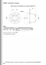
BMC motors base Motor base for installation of auxiliar y flange FP7 H1 28° TABLE 7 Bell housing dimensions, BMC motor base Electric motor, 4-pole, 1500 rpm Frame size 225 Motor base code Assembly kit code (base module + flange): KVG7 • For pump flange codes, see page 13 3D drawings available on website www.mpfiltri.com, under TOOLS/2D/3D CAD COMPONENTS 12
Open the catalog to page 12
TABLE 8 Flange Code Possible pump interfaces Possible pump interfaces Complete the order designation with the pump interface code: E.g. FP5026S023 3D drawings available on website www.mpfiltri.com, under TOOLS/2D/3D CAD COMPONENTS 13
Open the catalog to page 13All MP Filtri catalogs and technical brochures
 MULTI-COMPONENTS
31 Pages
 LMS/LDS Series
17 Pages
 LMC/LDC Series
17 Pages
 LMG Series
21 Pages
 ACCESSORIES
28 Pages
 BELL HOUSING
72 Pages
 CLOGGING INDICATORS
24 Pages
 COUPLINGS
46 Pages
 CONTAMINATION CONTROL SOLUTIONS
140 Pages
 Return / Suction Filters
76 Pages
 SPIN-ON FILTERS
76 Pages
 Stainless Steel Filters
102 Pages
 Low & Medium Pressure Filters
168 Pages
 High Pressure Filters
160 Pages
 Suction Filters
72 Pages
 Return Filters
230 Pages
 FHD - DUPLEX
17 Pages
 FHF 325 - MANIFOLD
14 Pages
 FHB - MANIFOLD
16 Pages
 FHM - MANIFOLD
21 Pages
 FHP
FHP19 Pages
 FMP
FMP14 Pages
 Spin-On Filter
78 Pages
 Stainless Steel
20 Pages
 LMP 124
6 Pages
 MRSX
MRSX12 Pages
 MSH
MSH4 Pages
 CS - CG - CW - CT
2 Pages
 MPS
MPS8 Pages
 LMP 952 - 954
6 Pages
 LMP 900 - 901
4 Pages
 LMD 400 - 401 - 431 DUPLEX
8 Pages
 LMP MULTIPORT
8 Pages
 FMM 050 - FHA 051
6 Pages
 FMP 039
4 Pages
 Clogging Indicators
26 Pages
 SF2 250 - 350
4 Pages
 Suction Strainer
7 Pages
 FRI
FRI10 Pages
 MPI
MPI8 Pages
 MPH
MPH18 Pages
 MPT
MPT15 Pages
 filter element CH
1 Page
 MST
MST4 Pages
 STR
STR4 Pages
 RF2
RF24 Pages
 MPF
MPF20 Pages
 LMP 400 - 430
10 Pages
 LMP 210
5 Pages
 LMP 110-120-123 MULTIPORT
25 Pages
 FAS
FAS4 Pages
 SF2 500
12 Pages
 SF2 250
8 Pages
 SA - SAP
10 Pages
 STR
STR4 Pages
 Condition monitoring products
14 Pages
 Pressure filters
116 Pages
 In-line filters
108 Pages
 Structural components
64 Pages
 Accessories
68 Pages
 Catalogue
19 Pages


- Liquid filter
- Level limit switch
- Filter with cartridge
- Liquid level detector
- Pressure separator filter
- Industrial use filter
- Plastic cap
- Cylindrical cap
- Stainless steel pre-filter
- Float level switch
- Y-strainer filter
- Compact pre-filter
- Liquids level gauge
- Hydraulic filter
- Basket filter
- Real-time monitoring module
- Measurement monitoring module
- In-line filter
- Magnetic float level switch
- Environmental monitoring system