

Moyno Grinders Service Manual

Moyno Grinders Service Manual
The Moyno 500 Pumps, specifically the 400 Series Grinder Pumps (models 41502, 42202, 43302, and 44402), feature a cast iron housing, chrome-plated AISI 416 stainless steel pump rotor, NBR (Nitrile) pump stator, AISI 416 stainless steel shaft, prelubricated fully sealed ball bearings, a mechanical seal (carbon/ceramic), hardened steel cutter ring, cast iron cutter disc, and carbide cutter tips.
The pump can be mounted in any position, but when mounted vertically, bearings should be above seals to prevent leakage. The pump is not self-priming, so elements must be below the water line. Piping should be self-supporting with a 4” NPT male connection on the suction port and a 1-1/4” NPT female connection on the discharge port. A non-clogging check valve is recommended in the discharge piping. The drive requires a 56 frame, C-face, 1 HP, 1750 rpm motor, and the pump rotation must be clockwise.
The pump is not self-priming and should not run dry. Maximum discharge pressure is 80 feet of water or 35 psig, and it operates between 10° to 160°F. For storage, the pump should be drained.
Common issues include failure to pump, pump overloads, failure to start, noisy operation, seal leakage, and grinder problems. Solutions involve checking motor and pump shaft connections, pressure levels, rotation direction, and ensuring proper assembly and lubrication.
Before disassembly, disconnect the power source and bleed pressure. The process involves removing various components such as the reducer, cutter assemblies, stator housing, rotor, mechanical seal, and bearings. Care should be taken to replace worn or broken parts, especially the mechanical seal.
Reassembly involves securing the adaptor plate and gasket, pressing bearings onto the shaft, installing the mechanical seal, and assembling the rotor, stator, and cutter components. Thread locking compounds should be used on screws, and the motor should be aligned and secured properly.
The document includes a detailed parts list for different pump models, specifying item numbers, descriptions, and part numbers. Recommended spare parts and repair/conversion kit numbers are also provided.
Catalog excerpts
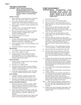
WARNING:Before making adjustments,disconnect power source andthoroughly bleed pressure fromsystem. Failure to do so could resultin electric shock or serious bodilyharm.Failure To Pump. > 1.Motor shaft turns; pump shaft will not: Check key,collar, and collar screw. Adjust if necessary.2.Torn stator; possibly excessive pressure:Replace stator, check pressure at discharge port.3.Wrong rotation: Rotation must be clockwise whenfacing shaft.4.Threads in rotor or on shaft stripped: Replacepart. Check for proper rotation.5.Rotor pin sheared at rotor connection: Possiblyexcessive pressure. Replace parts,...
Open the catalog to page 2
Pump Model Numbers Item No.Description4150242202Ɔ4330244402 1Pump Body > 350-0629-000 9Reducer > 330-4196-000 14Stator Housing > 350-0618-000 *21Stator > 340-3501-120340-3502-120340-3503-120340-3504-120 *22Rotor > 330-4605-000330-4604-000330-4603-000330-4602-000 26Drive Shaft > 340-2371-000 29Bearing > (2 req.)630-0502-061 40Adaptor Plate > 330-4201-000 46Rotor Pin > 320-4486-003320-4486-004 66Snap Ring > 320-2794-000 *69Mechanical Seal > 320-6500-000 77Slinger Ring > 320-6385-000 79Adaptor Plate Gasket > 320-5888-000 *83Reducer Gasket > 320-5878-000 112AScrew, SS Cap > (8 req.)320-4787-006 (8-32...
Open the catalog to page 3
When ordering parts , please specifypump model number, pump serial number,part number, part description and quantity. >
Open the catalog to page 4
CAUTION: Be sure to use a thread lockingcompound on threads of screws (112A). > Secure adaptor plate gasket (79) and adaptorplate (40) to pump body (1) using lock washers (215B) and screws (112C). > Install cutter ring (196) and cutter tip/cutter clampassemblies using the following procedure: > Press bearings (29) on shaft (26), and locateslinger ring (77) near bearing on threaded end of shaft. > Place cutter ring (196) in stator housing (14). > Position cutter tip/cutter clamp assemblies on cutter ring, screwing screw (112D) finger tight. Cutter tip/cutter clamp assemblies should point to center...
Open the catalog to page 5
1999 by Moyno, Inc.ɮ Moyno is a registered trademark of Moyno, Inc.Printed in U.S.A. >
Open the catalog to page 6All Moyno catalogs and technical brochures
 EZstrip™ Hose Pump
16 Pages
 EZstrip Cake Pump
2 Pages
 SERIES A
2 Pages
 Dosing pump
2 Pages
 Hygienic Pump
2 Pages
 Mine Dewatering
2 Pages
 InviziQ™
2 Pages
 EZstrip™ TR Muncher
2 Pages
 L-Frame
2 Pages
 EZstrip? Transfer Pump
2 Pages
 Epsilon/Vertical
2 Pages
 2000 Pumps
2 Pages
 Compact C
2 Pages
 Small Pumps
2 Pages
 Moyno 1000 Brochure
6 Pages
 Moyno 1000 Pumps Bulletin
2 Pages
 Moyno 500 Pumps Bulletin
2 Pages
 Water/Wastewater Brochure
8 Pages

Archived catalogs
 EZstrip™ Cake Pump
2 Pages
 Moyno 500 Pumps Selection
4 Pages
 Moyno 500 Pumps Brochure
6 Pages
 Moyno Metering Pumps Specs
4 Pages
 Moyno Grinders Specs
2 Pages
 Moyno Grinders Brochure
8 Pages
 Moyno 2000 CC Service Manual
16 Pages
 Moyno 2000 CC Brochure
8 Pages
 Moyno 1000 Service Manual
34 Pages


