


Electric motors - Technical catalogue - M/2011/REV.2 - IT+EN+FR+DE+ES+CN

Electric motors - Technical catalogue - M/2011/REV.2 - IT+EN+FR+DE+ES+CN
This document provides detailed information on the physical measurements, conversion factors, and operational formulas related to electric motors. It includes specifications, procedures, and standards for understanding and utilizing electric motors effectively.
The document outlines various conversion factors between the International System of Units (SI) and the Anglo-Saxon system. Key conversions include:
- 1 horsepower (hp) = 745.7 watts (W)
- 1 lbf·ft/s = 1.356 W
- 1 W = 0.00134 hp
- 1 W = 0.738 ft·lbf/s
The document provides formulas related to motor operation, including:
- Phase voltage and current: V = √3E, IV = IE/√3
- Speed of rotation: n = (60/2π)·w = 9.55·w
- Force and weight force: F = m·a, P = m·9.81
- Moment: M = F·r
- Linear power: P = F·V
- Angular power: P = M·w
- Energy: W = P·t
Nominal characteristics refer to the numerical values of electrical and mechanical properties of motors, such as power voltage, frequency, current, speed, and power delivery. These values are indicated on the motor's nameplate and are crucial for ensuring the motor operates under specified conditions.
The document explains the concept of synchronous speed (ws) and nominal speed (wn) of motor shafts, providing formulas to calculate these speeds based on the number of poles and frequency of the power supply.
The relationship between mechanical power output, torque, and rotational speed is given by P = T·w. The document also discusses power factor and electrical power absorbed by the motor, providing formulas for both three-phase and single-phase systems.
This document serves as a comprehensive guide for understanding the technical aspects of electric motors, including measurement conversions, operational formulas, and nominal characteristics. It is a valuable resource for engineers and technicians working with electric motors.
The document provides detailed specifications for electric motors, including nominal voltage (Vn), nominal current (In), starting current (Is), nominal torque (Mn), starting torque (Ms), minimum asynchronous torque (Mi), and maximum torque (Mmax). It also covers synchronous speed (ws, ns) and nominal speed (nn, wn).
Key formulas related to motor operation are provided, such as the relationship between power, torque, and speed: P [W] = T [Nm]·w [rad/s]. The document also explains how to calculate efficiency (h = P / Pa) and provides formulas for calculating mechanical power output and electrical power absorbed.
The document outlines procedures for calculating acceleration and braking times, considering the inertia moment of the motor and the connected load. It provides formulas for both the SI system and practical system, emphasizing the importance of considering external loads connected via gear reducers or speed multipliers.
Recommendations are given for calculating the inertia moment and the impact of external loads on motor performance. The document stresses the need to adjust calculations based on the specific characteristics of the motor and load.
The document includes tables showing the relationship between the number of poles and RPM at different frequencies (50Hz and 60Hz), as well as the formulas for calculating synchronous speed based on the number of poles and nominal frequency.
Understanding the efficiency and power factor is crucial for optimizing motor performance. The document provides detailed explanations of how to calculate these parameters and their impact on motor operation.
Efficiency is defined as the ratio between measured power delivery and absorption, with a tolerance of -15% of (1-η). The power factor tolerance is -1/6 of (1-cosφ), with a minimum of 0.02 and a maximum of 0.07. Creep at full load and operating temperature has a tolerance of ±20% for power delivery over 1kW and ±30% for power delivery under 1kW. Current with a locked rotor and any specific starting device has a tolerance of 20%. Torque tolerances include -15% for locked rotor torque, 25% for sag torque, and -10% for maximum torque. The moment of inertia has a tolerance of ±10%, and the sound pressure level can vary by +3dBA. The height of the axis has a tolerance of -0.5mm, and flange centring diameter is specified as N J6. Shaft dimensions vary with a tolerance of j6 for diameters up to 28mm and k6 for those over 28mm. Key dimensions are specified as F x GD h9, with keyway width F N9.
The casing is made from die-cast aluminium alloy, known for its high tensile strength and corrosion resistance. It is finned and optionally painted. The casing is equipped with lifting rings from size 112 and is prepared for mounting feet opposite the terminal block. It includes a grounding clamp inside the terminal block, with an option for external grounding on the motor casing. The shaft is made from C40 steel or equivalent, with standardised dimensions according to IEC60072-1. It features a threaded hole on the driving side and an optional double-ended shaft. A hexagonal recess is provided on the non-drive side for manual rotation.
The rotor is a squirrel cage type, made from aluminium or aluminium alloy, designed to enhance starting torque in single-phase motors. The rotor's design ensures smooth operation even at variable speeds, reducing harmful torque pulsations. Balancing is performed dynamically according to ISO 2373 grade G6.3, with an option for a higher grade G2.3. The stator is made from low-loss magnetic laminations, with winding made from enameled copper of grade G2 and class H, providing high mechanical resistance and thermal reserve. The insulation system is class F, and all electrical parameters are tested 100% at the end of the assembly line.
The document outlines the specifications for electric motors, focusing on cable glands and plugs. It adheres to European Directive 80/181/CEE and subsequent amendments, ensuring dimensional standardization according to EN50262 and DIN42925 standards. Metric units are used for cable gland threads.
For all motor sizes, cable glands and nameplates can be positioned on either side of the motor. The B3 mounting position is standard, with the terminal block on the opposite side. Custom configurations with cable glands on the fan side are available upon request, requiring consultation with technical services.
The document provides detailed specifications for various motor sizes, including the number and type of cable glands and plugs installed. It specifies the tightening torque and diameter range for each motor size.
The motors use radial, single race ball bearings with normal play, lubricated for life. The drive side has 2Z shielding, while the non-drive side has 2Z or 2RS shielding, depending on the version. Rear bearings are pre-loaded with a compensation ring to reduce noise and allow axial movement due to thermal effects.
Details are provided for flange types B5 and B14, including dimensions and material specifications. Custom solutions for reduced or oversized flanges are available through technical consultation.
The document includes tables with technical data for motor sizes, flange dimensions, and bearing specifications, ensuring comprehensive coverage of the motor's design and operational parameters.
The document provides specifications for various electric motors, including static load coefficients (C0) and maximum radial and axial loads at 50Hz. It lists motor sizes and their corresponding load capacities, highlighting the importance of installation orientation on load values.
For belt/pulley coupling, the document outlines a formula to calculate the radial load (FR) on the motor shaft, considering factors like nominal motor power (Pn), pulley weight (PP), speed (n), and pulley diameter (Dp). The coefficient (K) varies between 2 and 3 based on the transmission type.
The document references IEC 34-7 for motor mounting positions and IEC 60034-5 for protection degrees. It specifies that standard Motovario electric motors have a protection degree of IP55, with options for higher protection levels upon request.
It is crucial to consider the installation type (horizontal or vertical) and mounting equipment when positioning motors. For vertical installations with the shaft end uppermost, specific load values must be inverted.
The document details various mounting positions, including with feet, drive side flange, and combinations thereof. It emphasizes the importance of selecting the appropriate mounting position based on the motor's application and environment.
The tables provide detailed load capacities for different motor sizes and configurations, as well as installation methods and protection degrees. These data points are critical for selecting the right motor for specific applications.
The document outlines the protection ratings for electric motors, focusing on the protection provided by the enclosure against contact with live components, ingress of solid foreign matter, and water damage. It does not cover mechanical damage or special conditions like humidity, corrosive vapors, or explosive atmospheres. The protection rating is indicated by the letters 'IP' followed by two digits.
- Motovario standard electric motors have a protection rating of IP55, with optional ratings of IP56, IP65, and IP66 available. Ratings above IP66 are not provided.
- Motovario brake motors have a standard rating of IP54, with an optional upgrade to IP55 using a protection kit.
First Digit (Solid Matter Protection):
- 0: No protection
- 1: Protection against solid objects >50mm
- 2: Protection against solid objects >12mm
- 3: Protection against solid objects >2.5mm
- 4: Protection against solid objects >1mm
- 5: Dust protection (not complete, but sufficient to prevent motor malfunction)
- 6: Total dust protection
- 0: No protection
- 1: Protection against vertically falling water drops
- 2: Protection against vertically falling water drops when tilted up to 15°
- 3: Protection against water falling at an angle up to 60°
- 4: Protection against water splashes from any direction
- 5: Protection against water jets from any direction
- 6: Protection against powerful water jets
- 7: Protection against water ingress when submerged under specific conditions
- 8: Suitable for continuous submersion in water under conditions specified by the manufacturer
The thermal insulation system for electric motors is classified by a letter according to IEC85. The document specifies the maximum allowable temperatures for different thermal classes, with standard motors conforming to insulation class F. However, the thermal reserve is designed to ensure that the temperature does not exceed class B limits, extending motor lifespan. Higher insulation classes, such as H, can be provided upon request based on installation environment.
The document outlines the specifications for electric motors under various environmental conditions. It includes details on low and high temperature constructions, condensation heaters, and efficiency standards.
Motors designed for low temperatures are equipped with special components such as bearings with special lubrication (LHT) and higher backlash (C3), silicone oil seals, aluminum fans, and metal cable glands and plugs. These motors are not compatible with forced ventilation or certain brake motors unless they have an IP55 protection rating.
Motors for high temperatures include class H winding insulation, bearings with special lubrication (LHT) and higher backlash (C3), Viton/FKM seal rings, aluminum fans, and metal cable glands and plugs. Power derating is recommended for ambient temperatures of +60°C. These motors are also not compatible with forced ventilation or brake motors.
For motors with a DC power source, the same heating effect as condensation heaters can be achieved by powering two phases of the motor when it is off. The formula provided is Vdc = √(P∙R), where P is the heating power in watts and R is the resistance between two phases.
The document describes two series of motors: the standard efficiency TS series and the high efficiency TH series. The TS series includes motors with 2, 4, 6, or 8 poles, with nominal powers from 0.09 kW to 11 kW, conforming to IE1 efficiency levels. The TH series offers high efficiency with 2, 4, or 6 poles, nominal power from 0.75 to 9.2 kW, conforming to IE2 efficiency levels. Construction differences include larger active components and low-loss insulated magnetic lamination.
The document emphasizes the importance of selecting the appropriate motor construction based on environmental conditions to ensure optimal performance and longevity.
- TS Series: Standard efficiency motors available in 2, 4, 6, or 8 poles, with power ratings from 0.09 kW to 11 kW. These motors comply with IE1 efficiency levels, equivalent to Eff2 under the CEMEP agreement.
- TH Series: High-efficiency motors with 2, 4, or 6 poles, power ratings from 0.75 kW to 9.2 kW, and comply with IE2 efficiency levels, equivalent to Eff1 under the CEMEP agreement. They feature larger active parts and low-loss insulated magnetic sheets.
- TH motors have larger stators and rotors, and increased copper content compared to TS motors.
- Both series maintain similar external dimensions, with specific exceptions for certain power ratings and pole configurations.
- As of June 16, 2011, per European Commission Regulation 640/2009, motors must meet at least IE2 efficiency to be marketed, excluding certain categories like brake motors and those integrated into other products.
- Standard voltage and frequency for motors are specified with tolerances: 230/400V 50Hz for single polarity three-phase motors, 400V 50Hz for double polarity, and 230V 50Hz for single-phase motors.
Standard motors (Euro Voltage) are designed for specific voltage and frequency ranges:
- Single polarity three-phase motors: 230/400V 50Hz with a 10% voltage tolerance.
- Double polarity three-phase motors: 400V 50Hz with a 10% voltage tolerance.
- Single-phase motors: 230V 50Hz with a 5% voltage tolerance.
For single polarity three-phase motors, the nominal power at 60Hz is 15-20% higher for TS series motors compared to their 50Hz ratings. TH series motors maintain the same nominal power at both frequencies. A 10% tolerance is guaranteed for all voltage/frequency values.
These motors can operate on 60Hz power, delivering 15-20% more power at 460V 60Hz compared to 50Hz, while maintaining other catalogue ratings approximately. The operational characteristics change based on the supply voltage compared to 50Hz values.
Motors can be customized for non-standard voltages/frequencies. The winding is non-standard, and the nominal power at 60Hz is indicated as "M" (15-20% higher), while "S" indicates the standard 50Hz power.
These motors generally cannot be used on 60Hz networks without a custom electrical design.
The document discusses single-pole three-phase motors with standard efficiency (TS series) designed for voltages 220/380V, 230/400V, or 240/415V at 60Hz. These motors use standard windings (Euro voltage) but may experience reduced performance, particularly in starting torque. If standard performance is insufficient, motors with higher power can be ordered with custom windings.
For single-pole three-phase motors, supply voltages of 220/380V±5% 50Hz and 240/415V±5% 50Hz fall within the range of 230/400V±10% 50Hz. These are equipped with standard windings. Motors can be supplied with a ±10% tolerance on request.
Standard single-phase motors (Euro voltage) are not generally suitable for 60Hz networks without specific electrical design modifications (winding and capacitor changes).
Motors with non-standard supply voltages (SP1 - optional) can be manufactured to operate with different voltages and frequencies. The standard nominal power at 50Hz is indicated as "S," while "M" denotes increased nominal power (15-20%) at 60Hz. TH series motors are not available with increased power at 60Hz.
High efficiency motors (TH series) for voltages 220/380V, 230/400V, or 240/415V at 60Hz are always made with custom windings and are not available with over-rated power. These motors are typically equipped with a 6-terminal winding suitable for D/Y connection. For the US market, UL/CSA approved motors can be ordered for 230/460V 60Hz with a 9-terminal winding for YY/Y connection.
The document provides normal production values for the mean sound pressure level LpA [dB(A)] for three-phase motors running under no load at 50Hz, measured per ISO R 1680 with a tolerance of +3dB(A). At 60Hz, values increase by approximately 2dB(A). Measurements are taken in a semi-anechoic chamber at 1m from the motor's housing.
The document provides standard values for the average sound pressure level (LpA) in dB(A) for three-phase motors operating at no load with a supply frequency of 50 Hz. Measurements are taken in a semi-anechoic chamber at a distance of 1 meter from the motor's external surface. The values are compliant with ISO R 1680 standards, with a tolerance of +3 dB(A). At 60 Hz, values increase by approximately 2 dB(A). The motors are standard, totally enclosed with external surface ventilation (IC411 method according to IEC 60034-6).
The document defines 'duty' as the load condition a machine is subjected to, including periods of starting, electrical braking, no-load operation, and rest. Duty types are standardized according to IEC 60034-1, with S1 being the default if unspecified. The duty type is indicated on the motor's nameplate.
- S1 Continuous Duty: Operation at constant load for a duration sufficient to achieve thermal equilibrium. Users must specify load and nominal operating conditions for unlimited operation.
- S2 Limited Duration Duty: Operation at constant load for a limited time, less than required for thermal equilibrium, followed by a rest period to equalize machine and coolant temperatures within a 2°C tolerance. Designated as S2 followed by running time (e.g., S2 30 min).
- S3 Periodic Intermittent Duty: Identical cycles of operation at constant load and rest, where starting current does not significantly affect overtemperature. Designated as S3 followed by the intermittency ratio, calculated over a 10-minute cycle (e.g., S3 25%).
1. Trip temperatures for insulated motors: 130°C for class F, 140°C for class F with UL/CSA approval, and 150°C for class H. Tolerance of ±5°C.
2. Insulation dielectric strength: 2KV.
3. Compliance with IEC60034-11.
4. Custom trip temperatures available between 70 and 180°C.
Bimetallic thermal protectors are normally closed (NC) contacts that open when a set temperature is reached, used to control a relay that interrupts power, ensuring the circuit opens before exceeding the maximum winding temperature as per IEC60034-1. Typically, three protectors are used in series for three-phase motors, and one for single-phase motors. Normally open (NO) protectors are available on request.
1. Type: NC.
2. Trip temperature: 130°C for class F, 140°C for class F with UL/CSA, 150°C for class H. Tolerance: ±5°C.
3. Insulation dielectric strength: 2KV.
4. Compliance with IEC60034-11.
5. Custom trip temperatures available between 70 and 180°C.
Thermistors are temperature sensors with high sensitivity, typically with a positive temperature coefficient (PTC), where resistance increases sharply near the trip temperature. They function similarly to bimetal cutouts, with the resistance signal used to trip a motor protection device.
1. Trip temperature: 130°C for class F motors, also valid for UL/CSA; 150°C for class H motors.
2. Insulation dielectric rigidity: 2.5KV.
3. Custom trip temperatures available between 60 and 180°C.
Standard asynchronous three-phase motors can be used in variable speed applications with inverters, adhering to IEC 60034-1. They feature robust electromagnetic specifications and insulation systems, allowing good performance under overloads and frequency limits. Phase separators ensure insulation resistance to voltage peaks from inverters. Applications with extreme speeds may require forced ventilation for cooling and noise reduction. For speeds above 3600rpm, consultation with technical service is advised.
1. Constant torque range: constant V/f ratio, allowing nominal torque operation down to a lower limit (approx. 30 Hz for self-ventilated motors in S1 duty, 2 Hz for S3 or S2 duty, or with forced ventilation in S1 duty). Below this, torque is derated as shown in the graph.
The document discusses the use of forced ventilation (IC416) for electric motors, particularly when operating at speeds significantly lower or higher than the nominal speed. It specifies the power supply options for single-phase (230V 50-60Hz) and three-phase (400V 50-60Hz) motors, with sizes ranging from 63 to 132.
To convert a standard self-ventilated motor (IC411) to a forced ventilated motor (IC416), the document outlines a step-by-step process: disassemble the standard fan cover, remove the plastic fan, and install the forced ventilation kit using the existing screws.
Forced ventilation is recommended for motors operating at speeds where standard fan cooling is insufficient or where ventilation losses become significant. The document advises using a protective cover for outdoor applications to prevent water ingress and obstruction from solid particles.
Forced ventilation is not available for motors with protection ratings above IP55 or for those used in high/low temperature or humid environments. The application of the forced ventilation kit results in a change in motor length.
The document includes dimensional tables indicating the changes in motor length when the forced ventilation kit is applied. It also specifies the connector type (mPm B202000N2 DIN 43650-A/ISO 4400) and cable entry specifications (M16x1.5, diameter 5-10 mm).
The document outlines the specifications for electric motors, focusing on connection types and configurations. It specifies the use of 10-pole connectors for standard three-phase motors and high-starting torque single-phase motors, and 5-pole connectors for single-phase motors with or without thermal protection. The motors are designed to operate at a nominal voltage of 400V and frequency of 50Hz, with insulation class F and continuous duty S1.
For changing the direction of rotation, the document provides procedures for both three-phase and single-phase motors. For three-phase motors, swapping two supply phases is required, while for single-phase motors, altering the terminal board connections as per wiring diagrams is necessary. It is emphasized that internal connections should not be altered.
The connections and direction of rotation comply with the IEC60034-8 standard. The default direction of rotation is clockwise, and all standard motors are suitable for operation in both directions.
Motors with rapid connection power supply are available up to a nominal power of 4 kW and size 112. Brake motors with rapid connections are available in IP54 protection, with higher protection levels available on request.
The tables provide dimensions for different motor sizes and connector types, indicating compatibility with various motor series. The technical data in the catalogue tables refer to standard three-phase asynchronous motors with specific insulation and operational characteristics.
The document provides technical data for three-phase asynchronous motors in standard execution, with class F insulation and continuous duty S1, powered at a nominal voltage of 400V and frequency of 50Hz. The connection types are indicated inside the terminal box cover, with a conventional clockwise rotation achieved by supplying the terminals U-V-W with direct network voltages L1-L2-L3.
The TS and TH series motors are available in standard 6-terminal and 9-terminal constructions. The 9-terminal version is designed for the North American market.
The D series motors are used in applications requiring two fixed speeds, achieved by switching the motor poles. There are two types: motors with a polarity ratio of 2 (2/4 poles, 4/8 poles) using a single winding and Dahlander YY-D connection, and motors with a different polarity ratio (e.g., 2/8 poles) with two distinct windings and Y or D connection. Special attention is needed during polarity switching due to the braking torque applied, which can affect the motor's operation and transmission sizing.
The S series motors are single-phase asynchronous motors with a running capacitor, insulated in class F, and continuous duty S1, powered at 230V and 50Hz. They have two separate windings, allowing for rotation direction reversal by modifying terminal connections or using contactors. An optional balanced winding version is available for low-powered motors, allowing external rotation direction change with a switch.
The document discusses single-phase electric motors, specifically the S series and HSE series. The S series motors have two windings: a main winding covering 2/3 of the stator slots and an auxiliary winding covering 1/3. These motors allow for rotation reversal by altering connections or using external switches. An alternative balanced winding option is available, with identical windings each covering half the stator slots, suitable for small power motors (sizes 63/71/80).
For the S series, rotation direction can be reversed externally using a switch with positions 0-1-2, eliminating the need for two external switches. The HSE series motors are designed for high starting torque applications and include an auxiliary capacitor activated only during startup, which is disconnected once full speed is reached.
The motors are designed for a nominal voltage of 230V and frequency of 50Hz, with a permissible voltage tolerance of ±5%. Special windings for 60Hz frequency are available upon request.
The HSE series motors are recommended for applications requiring high starting torque, such as compressors and centrifugal pumps. The electronic cutout in HSE motors allows for safe starting under load by disconnecting the auxiliary capacitor only when a certain voltage is reached, ensuring the motor has effectively started.
The document includes a graph comparing starting torques of single-phase and three-phase motors, highlighting the effectiveness of the auxiliary capacitor in achieving comparable starting torques.
The HSE series offers competitive advantages over centrifugal cutout solutions, as it does not require special components and maintains the same dimensions as standard motors, except for the presence of capacitors.
- Standard incremental encoders have a resolution of 1024 pulses per cycle and are available in Push-Pull (HTL) and Line Driver (TTL) versions. They can operate at a maximum speed of 9000 rpm and have a protection rating up to IP65.
- Low-resolution incremental encoders are available for motor sizes 63-71-80-90, with resolutions of 13 or 15 pulses per cycle depending on the size. They have a protection rating up to IP66 and operate at a maximum frequency of 12.6 kHz.
- Standard encoders are mounted by locking the rotor directly onto the motor shaft, with the stator held in place by a locking pawl. This setup allows for axial elasticity to compensate for play and dampen vibrations.
- Low-resolution encoders use a magnetic stainless steel phonic wheel and Hall effect sensors to determine motor speed and direction.
- Encoders should be selected based on the required resolution and environmental protection needs. The installation of standard encoders affects motor dimensions, which should be considered during design.
- Low-resolution encoders do not alter motor dimensions, making them suitable for applications where space is a constraint.
- Standard encoders: 1024 pulses/cycle, 10-32 V (HTL) or 5 V (TTL), max speed 9000 rpm, operating temperature -30°C to +100°C.
- Low-resolution encoders: 13-15 pulses/cycle, 10-30 V (NPN), max frequency 12.6 kHz, operating temperature -40°C to +90°C.
- Protection level up to IP65, matching the motor's protection.
- Maximum rotation speed: 9000 rpm.
- Operating temperature range: -30°C to +100°C.
- Maximum power consumption under load: 30 mA; without load: 40 mA.
- Maximum usage frequency: 300 kHz.
- Incremental encoders available with electronics (HTL or TTL) and customizable pulse/revolution count (1 to 65536).
- Standard resolution: 1024 pulses/revolution.
- Push-Pull (HTL) version with 10-32 V supply or Line Driver (TTL) with 5 V supply.
- Available without connector (free cables) or with optional M23 12-pin male connector.
- Available for three-phase motors sizes 63-71-80-90, with or without brake; optional for sizes 100-112-132.
- Composed of an encoder board and a magnetic steel tone wheel.
- Two Hall-effect sensors detect the tone wheel's passage, with output signals offset by 90° to determine rotation direction.
- Standard resolution: 13 pulses/revolution for motor size 63, 15 for sizes 71-80-90.
- NPN version with 10-30 V supply; PNP and Push-Pull versions available on request.
- Protection level up to IP66, matching the motor's protection.
- Operating temperature: -40°C to +90°C.
- Maximum power consumption under load: 25 mA; maximum usage frequency: 12.6 kHz.
- Standard motors (TS, TH, D series) can be converted to brake motors (TBS, TBH, DB series) for quick and safe stopping.
- Electromagnetic brakes available in various versions for different applications.
- FM Brake: DC supply, negative action, suitable for smooth, silent, and gradual operations.
- MS Brake: AC supply, negative action, suitable for rapid and precise braking.
- ML Brake: DC supply, negative action, suitable for smooth braking with high load capacity per cycle.
- Negative action: braking occurs without power supply.
- Motovario typically supplies brake motors with FM type DC brakes unless specified otherwise.
The document provides detailed specifications for FM brakes, which are DC electromagnetic brakes. Key parameters include brake release times with different rectifiers, nominal and maximum air gaps, and available braking moments. The brakes operate with a power supply of 230V±10% or 400V±10% at 50/60Hz, with other voltages available as options. The brakes have a standard protection rating of IP54, with an option for IP55 for special conditions.
The FM brake system consists of several components including a brake magnet, moving coil, brake disk, drive hub, thrust springs, and optional components like a release lever and protective boot. The system also includes various mounting and adjustment hardware.
The FM brake functions by using spring pressure to engage the brake when there is no power supply. When powered, the brake magnet attracts the moving coil, allowing the brake disk to rotate freely. Upon power loss, the springs press the moving coil and disk against the motor shield to stop the motor.
The brakes feature silent, asbestos-free friction surfaces with double braking surfaces. The braking moment is fixed and selected based on the nominal motor torque, with options for adjustable braking moments. The system includes a steel disk brake sliding on a splined drive hub and a vibration damping O-ring.
Optional features include a manual release lever with automatic return, which can be useful during power outages or installation. An anti-seizing stainless steel washer is available to prevent the brake disk from seizing to the motor shield during long periods of disuse.
The document notes that actual values may vary slightly due to environmental conditions and wear. A running-in period is required for the brake to adapt to the motor shield surface, with a deviation of ±15% from declared values expected after this period.
The document describes the ML brake, a DC electromagnetic brake that operates without power supply through spring pressure. It is designed for use with electric motors and has a standard protection rating of IP54. The brake's power voltage is 230V±10% 50/60Hz or 400V±10% 50/60Hz, with a fixed braking moment set according to motor size.
The brake is powered by direct current through a rectifier bridge, converting single-phase AC input to DC. For TBS and TBH series motors, the standard input voltage is 230V AC, rectified to 103V DC. For DB series motors, the input is 400V AC, rectified to 178V DC. The brake can be powered directly from the motor or separately from an external source.
Optional features include a manual release lever with automatic return, useful for manual operations during power outages or installation, and a microswitch to signal brake locking/releasing and wear. Brakes can also be supplied for various voltages, and different rectifiers are available for specific applications.
The document specifies that the braking moment is not adjustable and highlights the importance of using the correct rectifier type for the application. It also notes that all rectifiers, except the RRSD type, are available in versions compliant with UL/CSA standards.
The document includes tables with characteristic values for the brake, detailing the braking moment (MB) for different motor sizes and the specifications for various rectifiers, including their impact on release and braking times.
- Direct Brake Power: The brake coil is activated automatically when the motor is powered, and the brake disconnects. Upon motor power disconnection, the brake re-engages. The braking response time is influenced by the motor's inertia and stored energy, which varies per motor and cannot be predetermined.
- Separate Brake Power: The brake is powered via a rectifier from terminals separate from the motor. The stop time is independent of motor and load characteristics.
- Direct Brake Power with DC Side Opening: This setup allows for rapid braking contact on the rectifier, making the braking response time independent of motor and load characteristics and shorter than separate power setups.
- Separate Brake Power with AC and DC Side Opening: Similar to the direct power setup, this configuration prevents energy discharge into the rectifier during braking, extending its lifespan.
- Brake Magnet
- Moving Coil
- Brake Disk
- Drive Hub
- Optional Release Lever
- Optional Boot + O-ring
- Thrust Springs
- Optional V-ring
- Mounting Bolt
- Locknuts
- Optional Braking Torque Adjuster Screw
- Key
- Circlip
- Cast Iron Shield
- Vibration Damping O-ring
- Optional Anti-seizing Stainless Steel Washer
- Nominal Airgap (Sn)
- Maximum Airgap (Smax)
- Release Lever Play (X)
- Brake Disk Moment of Inertia (JB)
- Maximum Energy Dissipated by Brake (W)
- Energy Dissipated Between Airgap Adjustments (W1)
- Brake Release Time (t1)
- Brake Response Time (t2)
- Weight (mB)
- Power Absorption (Pa)
- Available Brake Moments (MB)
- Motovario supplies brakes with direct or separate power connections. Rapid release rectifiers (SBR) can reduce brake release time significantly.
- Independent DC power supply setups should use a fly terminal board for connections, with operation times similar to separate power setups.
The MS brake is an AC electromagnetic brake that operates without power through spring pressure. Standard power supply is 230/400V±10% 50Hz, with options for other voltages. It features a silent, asbestos-free friction joint with dual braking surfaces and a sliding steel brake disc on a splined hub. The braking torque is fixed based on the motor's nominal torque, with adjustable options available.
When powered, the brake coil energizes, overcoming spring force and allowing motor shaft rotation. Upon power loss, springs press the brake disc against the motor shield, initiating braking.
Manual release lever with automatic return, stainless steel anti-sticking ring, and IP55 protection for special environmental conditions. Separate brake power supply is available, with a second terminal block for brake cables.
Direct brake power is derived from the motor's terminal block, with automatic brake release upon motor power-up. Separate brake power is an option, affecting only brake characteristics.
Direct brake power involves energizing the brake coil with motor power, while separate brake power uses an auxiliary terminal block, affecting response times t1 and t2 based on brake characteristics alone.
The document outlines the specifications and calculations necessary for determining the braking moment (MB) for brake motors. The key factors influencing the brake's rating include the moment of inertia to be braked, the number of braking cycles per hour, the severity of the duty, and the required stopping times. The braking moment is calculated using the formula:
MB = K [(2π·n0/60) · Jtot ·± ML] / tFwhere K is the safety coefficient (≥2), Jtot is the total inertia of rotating parts reduced to the motor shaft, n0 is the motor shaft speed, tF is the braking time, and ML is the moment of load acting on the system.
The document emphasizes the importance of considering the wear of friction surfaces in relation to service intervals and the thermal load, which is the work that can be dissipated by the brake in relation to the load's moment of inertia and the number of cycles per hour. Special ambient conditions may require additional protections or corrosion proofing.
Each cycle transforms the energy of moving masses into heat by friction. The work done during braking (WB) is calculated, and the number of cycles per hour (Z) must be less than the maximum permissible for the selected brake type. If the calculated starting frequency (Z) exceeds the permissible limit, adjustments must be made to reduce the starting frequency or oversize the brake.
The maximum starting frequency (Z) is determined based on the load and inertias using the formula:
Z = KJ KM Z0where KJ and KM are coefficients related to the moment of inertia of the motor and load, MS is the motor starting torque, and Z0 is the starting frequency under load and inertia conditions. The calculated starting frequency must be less than the maximum number of cycles/hour allowed for the brake.
If the starting frequency is close to the maximum permissible, it is recommended to monitor the motor windings' temperature using a bimetal cutout to prevent overheating.
The document outlines the calculations for brake work and frequency in electric motors. It emphasizes that the maximum allowable work (WBmax) must exceed the calculated work. The number of permissible braking operations between two settings is determined by the formula N = W1 / WB, where W1 is derived from the brake type table.
The maximum starting frequency (Z) is calculated based on load and inertia using the formula Z = KJ KM Z0 [h-1]. The coefficients KJ and KM are obtained from tables, and Z0 is the starting frequency without load. The calculated Z must be less than the maximum allowable braking operations per hour. If not, the brake cannot dissipate the generated heat, necessitating a reduction in starting frequency or an oversized brake.
During each cycle, the energy of moving masses is converted into heat through friction. The braking work (WB) is calculated, and the number of cycles per hour (Z) must be less than the maximum allowable cycles for the selected brake type. If Z approaches Z0, motor winding temperature should be monitored using a bimetal thermal protector.
The document lists various optional constructions and accessories for electric motors, including different flange types, protection ratings, insulation classes, and additional features like condensation heaters, bimetal cutouts, and PTC thermistors. It also covers optional power voltages and compliance with standards like UL/CSA and ATEX II 3GD.
Details are provided for motors with FM, ML, and MS brakes, including separate power supplies, special brake coil voltages, manual release levers, and various kits for forced ventilation and encoders. Standard brake coil voltages are specified for different brake types.
- Various ventilation kits are available, including single-phase and three-phase options, depending on motor size.
- Incremental encoders are offered with or without connectors, and in low resolution for specific sizes.
- Motors can be equipped with different types of brakes (FM, ML, MS), each with specific features such as separate power supply, special brake voltage, manual release lever, and motor paint job.
- Standard brake coil voltages are specified for different brake types.
- Identification includes serial number, year of manufacture, motor type code, insulation class, and more.
- Details such as maximum ambient operating temperature, protection rating, and cooling system are provided.
- Additional options and features are noted, including anti-condensation heaters and thermoprotectors.
- Options include anti-condensation heaters for different voltages, execution for humid or extreme temperatures, and various protective devices.
- Motors can be equipped with encoders, flywheels, and quick connection systems.
This section provides a detailed identification guide for electric motors, including various cooling methods and additional options available for customization. The cooling methods are categorized as Totally Enclosed Fan Cooled (TEFC), Totally Enclosed Not Ventilated (TENV), and Totally Enclosed Blower Cooled (TEBC), each corresponding to specific IC codes (IC411, IC410, IC416 respectively).
Several additional options are available for electric motors, such as condensation heaters for different voltages (110V and 230V), constructions for humid, low, and high-temperature environments, bimetal cutouts, thermistors, backstop devices for directional rotation, encoders, flywheels, and rapid connection features.
The document explains the meaning of various symbols and abbreviations used in performance tables. Key parameters include nominal power (Pn), nominal speed (nn), nominal current (In), nominal torque (Mn), efficiency (η%), power factor (cosφn), and various torque and current ratios. It also covers motor moment of inertia (JT), motor weight (WT), no-load starting frequency (Z0), brake moment (MB), and capacitors for running and starting (Cr, Ca).
The document includes detailed performance tables for different motor sizes and specifications, highlighting parameters such as power, speed, current, torque, efficiency, and other critical performance metrics. These tables are essential for selecting the appropriate motor based on specific application requirements.
Catalog excerpts
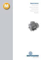
Motori elettrici Electric motors Moteurs electriques Motores electricos
Open the catalog to page 1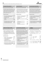
M Motori elettrici / Electric motors / Moteurs électriques / Elektromotoren / Motores eléctricos / 电动机 General features Caractéristiques générales Motori elettrici asincroni trifase e monofase, in esecuzione chiusa, ventilazione superficiale esterna, rotore a gabbia di alluminio o lega di alluminio pressofuso, classe di isolamento F, grado di protezione IP55, dimensioni e altezze d’asse unificate da 63 a 160, potenze unificate da 0,09 a 11kW. Three-phase and single-phase asynchronous electric motors, totally enclosed, with fan cooled ventilation, cage rotor in die-cast aluminium alloy or aluminium,...
Open the catalog to page 6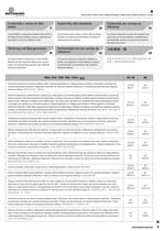
M Motori elettrici / Electric motors / Moteurs électriques / Elektromotoren / Motores eléctricos / 电动机 Conformità a norme di riferimento Conformity with standards Conformité aux normes de référence I motori elettrici in esecuzione standard sono conformi alle seguenti norme italiane, europee e internazionali riguardanti le macchine elettriche rotanti: The standard electric motors conform with the following Italian, European and international standards for rotating electrical machines: Les moteurs électriques en exécution standard sont conformes aux normes italiennes, européennes et internationales...
Open the catalog to page 7
M Motori elettrici / Electric motors / Moteurs électriques / Elektromotoren / Motores eléctricos / 电动机 The standard electric motors are in conformity with the following Directives: - Direttiva Bassa Tensione 2006/95/CE; - Direttiva EMC 2004/108/CE riguardante le caratteristiche intrinseche relative all’emissione e ai livelli di immunità; - Direttiva RoHS 2002/95/CE riguardante il divieto o la limitazione dell’uso di sostanze dannose negli equipaggiamenti elettrici ed elettronici; - Voltage Directive 2006/95/CE; Low - Directive EMC 2004/108/CE regarding intrinsic characteristics in relation to...
Open the catalog to page 8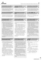
M Motori elettrici / Electric motors / Moteurs électriques / Elektromotoren / Motores eléctricos / 电动机 Conformità alle norme GOST Conformity with GOST standards Conformité aux normes GOST A richiesta, i motori serie TS, TH, TBS, TBH, D, DB, S, HSE possono essere realizzati in conformità alla normativa GOST-R per il mercato russo. On request, TS, TH, TBS, TBH, D, DB, S and HSE series motors can be constructed in conformity with the GOST-R directive for the Russian market. Sur demande, les moteurs des séries TS, TH, TBS, TBH, D, DB, S et HSE peuvent être réalisés en conformité à la norme GOST-R...
Open the catalog to page 9
M Motori elettrici / Electric motors / Moteurs électriques / Elektromotoren / Motores eléctricos / 电动机 M Note / Notes / Remarques / Aufzeichnung / Notas / 注释 8 www.motovario-group.com
Open the catalog to page 10
M Motori elettrici / Electric motors / Moteurs électriques / Elektromotoren / Motores eléctricos / 电动机 M Note / Notes / Remarques / Aufzeichnung / Notas / 注释 www.motovario-group.com 9
Open the catalog to page 11
M Motori elettrici / Electric motors / Moteurs électriques / Elektromotoren / Motores eléctricos / 电动机 Grandezze fisiche e fattori di conversione / Physical measurements and conversion factors / Grandeurs physiques et facteurs de conversion / Physische Größen und Umrechnungsfaktoren / Magnitudes físicas y factores de conversión / 物理测量和换算系数 Unità di misura Grandezza fisica Sistema Internazionale S.I. lunghezza m = metro velocità m/s massa kg = kilogrammo-massa densità kg/m3 momento d’inerzia kg·m2 forza N = newton kgf* = kilogrammo-forza momento meccanico energia pressione potenza Nm kgf·m* J...
Open the catalog to page 12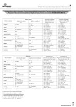
M Motori elettrici / Electric motors / Moteurs électriques / Elektromotoren / Motores eléctricos / 电动机 Grandezze fisiche e fattori di conversione / Physical measurements and conversion factors / Grandeurs physiques et facteurs de conversion / Physische Größen und Umrechnungsfaktoren / Magnitudes físicas y factores de conversión / 物理测量和换算系数 Unité de mesure Grandeur physique Système International S.I. longueur m = mètre vitesse m/s masse kg = kilogramme densité kg/m3 moment d'inertie kg·m2 force N = newton kgf* = kilogramme-force moment mécanique énergie pression puissance Nm kgf·m* J = Joule (=Nm)...
Open the catalog to page 13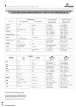
M Motori elettrici / Electric motors / Moteurs électriques / Elektromotoren / Motores eléctricos / 电动机 Grandezze fisiche e fattori di conversione / Physical measurements and conversion factors / Grandeurs physiques et facteurs de conversion / Physische Größen und Umrechnungsfaktoren / Magnitudes físicas y factores de conversión / 物理测量和换算系数 Unidad de medida Magnitud física Sistema Internacional S.I. longitud m = metro velocidad m/s masa kg = kilogramo-masa densidad kg/m3 momento de inercia kg·m2 fuerza N = newton kgf* = kilogramo-fuerza momento mecánico energía presión potencia Nm kgf·m* J = Joule...
Open the catalog to page 14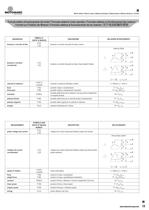
Motori elettrici / Electric motors / Moteurs electrlques / Elektromotoren / Motores electrlcos / Formule relative al funzionamento dei motori / Formulas related to motor operation / Formules relatives au fonctionnement des moteurs / Formeln zur Funktion der Motoren / Formulas relativas al funcionamiento de los motores / ^^&3tj#l^^i1£]i!!l tenslone e corrente dl fase tensione e corrente misurate tra fase e neutro sistema trifase tensione e corrente misurate tra fase e fase (sistemi trifase) velocita di rotazione dell'albero motore forza peso prodotto massa x accelerazione prodotto massa x accelerazione...
Open the catalog to page 15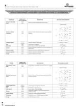
Motori elettrici / Electric motors / Moteurs electriques / Elektromotoren / Motores electricos / fczrfj^L Formule relative al funzionamento dei motori / Formulas related to motor operation / Formules relatives au fonctionnementdes moteurs/ Formeln zur Funktion der Motoren / Formulas relativas al funcionamiento de los motores / ^^fesfrtn^T^i^M RELATIONS INTERCURRENTES tension et intensite mesurees entre phase et neutre systeme triphase tension et intensite mesurees entre phase et phase (systemes vitesse de rotation de I'arbre moteur force polds produit masse x acceleration produit masse x acceleration...
Open the catalog to page 16All MOTOVARIO catalogs and technical brochures
 DEPLIANT PRODUCTS - M 2014
6 Pages
 DEPLIANT PRODUCTS - SD 2013
6 Pages
 PRODUCT BROCHURE - DV 2014
6 Pages
 Motovariators
151 Pages
 NMRX, SWX, SWFX
6 Pages
 Electric Motors
6 Pages



- DC electromotor
- Synchronous motor
- Alternating current motor
- Multipole motor
- Planetary gearbox
- Coaxial gearhead
- Electromotor for industrial applications
- Right angle gearhead
- Compact gearhead
- 4-pole motor
- 2-pole motor
- IP55 motor
- Hollow-shaft gearhead
- Gear train gear reducer
- Gearbox for industrial applications
- Induction motor
- 380 V motor
- Multi-stage gearhead