- Catalogs
- Motor Power Company
- Direct robot
Direct robot
1 /20Pages

Direct robot
1 /20Pages
Catalog excerpts

READY TO INSTALL AND PROGRAM MECHATROHICS POWER ^^^^^^^^^^^^^ COMPANY
Open the catalog to page 1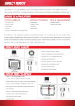
DIRECT ROBOT Direct Robot is a ready-to-install-and-program robot, based on direct drive standard linear modules of the series SKA Compact. Direct Robot is the effective solution for high dynamics, high precision applications with relevant load. RANGE OF APPLICATIONS MATERIAL HANDLING MATERIAL PROCESSING TEST & MEASUREMENT > PROBE CARRIER > VISUAL INSPECTION > PRODUCT STREAM DIVIDING AND GROUPING Direct Robot is a full embedded mechatronic device totally enclosed in its mechanical structure and provided with a motion package, including control, cabling and motion libraries. This configuration...
Open the catalog to page 2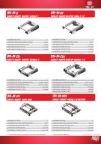
DIRECT ROBOT GANTRY SINGLE Y DIRECT ROBOT GANTRY SINGLE Y-Z > NUMBER OF AXES > MAXIMUM PAYLOAD HANGING DOWN > MAXIMUM DRUGGED PAYLOAD > MAXIMUM STROKE X AXIS > MAXIMUM STROKE Y AXIS > NUMBER OF AXES > MAXIMUM PAYLOAD HANGING DOWN > MAXIMUM DRUGGED PAYLOAD > MAXIMUM STROKE X AXIS > MAXIMUM STROKE Y AXIS > MAXIMUM STROKE Z AXIS DIRECT ROBOT DOUBLE SLIDE BAR DIRECT ROBOT SLIDE BAR DIRECT ROBOT GANTRY DOUBLE Y-Z DIRECT ROBOT GANTRY DOUBLE Y > NUMBER OF AXES > MAXIMUM PAYLOAD HANGING DOWN > MAXIMUM DRUGGED PAYLOAD > MAXIMUM STROKE X AXIS > MAXIMUM STROKE Y AXIS > NUMBER OF AXES > MAXIMUM PAYLOAD HANGING...
Open the catalog to page 3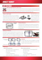
DIRECT ROBOT KEY FEATURES MD2 Technology (Mechatronic Direct Drive) Direct Robot is based on Direct Drive Technology. Mechatronic Direct Drive features real integration of mechanics, electronics, direct drive, control and motion software. The main axis are based on direct drive and are operated through robotic libraries properly set up to exploit the best of the SKA Compact axis performances, by providing a smooth and high dynamic motion. Ready to install module Hand terminal allows the user Gantry and Slide bar modules are set up and installed on to make a fast configuration and appropriate...
Open the catalog to page 4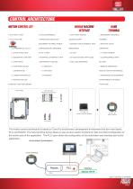
CONTROL ARCHITECTURE MOTION CONTROL SET HUMAN MACHINE INTEFACE HAND TERMINAL > FLAT FRONT DESIGN, ACCORDING TO DIRECT ROBOT > RUGGED TOUCH SCREENS, HIGH CONFIGURATION EXPANDIBLE > INTERFACE: ETHERNET TCP/IP > 10 FUNCTION KEYS WITH LEDS > TOOL LESS MOUNTING > ROBOTIC FUNCTION LIBRARY Direct Robot CPS_MS_(N)X Motion and Control Set CP_HMI_15 Human machine Interface The motion control architecture is based on Core Pro environment; development environment has two main layers: PLC and Robotic. The hand terminal device allows to use at once robotic functions for fast and direct configuration of the...
Open the catalog to page 5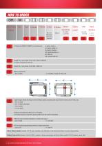
HOW TO ORDER DR M Direct Robot Model DIRECT ROBOT base moving tablescrew Choose the DIRECT ROBOT unit architecture Select the Y axis stroke. Enter 600 or 800 mm. Select the X axis stroke. Enter from 1000 to 4000mm. X stroke increases by 200 mm Cable lenght. Select the lenght of Direct Robot cable connecting the robot and the motion set CP_MS_(n)x > 00: no cable > 04: 4 meters (standard) > 06: 6 meters > 10:10 meters g: gantry single y gv: gantry single y-z 2g: gantry double y 2gv: gantry double y-z sb: slide bar sbb: double slide bar > 1: with MCS, model CP_MS_(n)X Fieldbus and Ethernet cables...
Open the catalog to page 6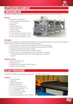
APPLICATION EXAMPLES UNSCRAMBLING Direct Robot is applied as unscrambling function for symmetrical and asymmetrical bottles (h:100-350mm) >> Production up to 3000 ppm >> Fast size change through software >> Vision system >> Modularity >> Electrical actuators >> Reduced maintenance >> Small foot print >> Working versatility >> X axis maximum acceleration: 20 m/s2 >> Y axis maximum acceleration: 30 m/s2 >> Z axis nominal force: 950N @ 1.2 m/s Performance, modularity and exceptional high flexibility give to Direct Robot all features to be the most advantageous choice to fulfill the application requirements...
Open the catalog to page 7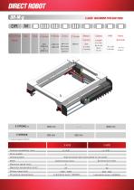
DIRECT ROBOT DR-M-g 3 AXES MAXIMUM PAYLOAD 25KG Direct Robot base moving Hand Terminal X AXIS P osition rep eta bility ( m m ) D rive system High precision ball recirculated on rail guide Maximum a ccele rati on ( m / s ) 2 S t roke ra ng e (mm) P reven tive main ten anc e
Open the catalog to page 8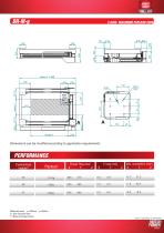
3 AXES MAXIMUM PAYLOAD 25KG Dimensions can be modified according to application requirements PERFORMANCE Travel Time (ms)* X Y Z Cycle/minute module** Reference travel x= 1000mm; y= 600mm (*) One way travel time (**) Back and forward travel
Open the catalog to page 9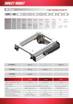
DIRECT ROBOT DR-M-gv DR-M-gv DR Direct Robot 4 AXES 4MAXIMUM PAYLOAD 7KG AXES MAXIMUM PAYLOAD 7KG 00: no axis R0: clamped base moving tablescrew Cables Lenght Motion Control Hand Terminal D rive system S liding syste m Synchronous linear Maximum spe ed (m/ s ) Maximum a ccele rati on ( m / s ) 2 S t roke ra ng e (mm) P reven tive main ten anc e (*) Z axis lubrication must be executed at any X/Y axes greasing
Open the catalog to page 10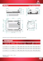
4 AXES MAXIMUM PAYLOAD 7KG Dimensions can be modified according to application requirements PERFORMANCE Travel Time (ms)* X Y Z Cycle/minute module** Reference travel x= 1000mm; y= 600mm; z= 100mm (*) One way travel time (**) Back and forward travel
Open the catalog to page 11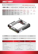
Direct Robot 6 AXES MAXIMUM PAYLOAD 25KG+25KG base moving Hand Terminal X AXIS P osition rep eta bility ( m m ) D rive system High precision ball recirculated on rail guide Maximum a ccele rati on ( m / s ) 2 S t roke ra ng e (mm) P reven tive main ten anc e
Open the catalog to page 12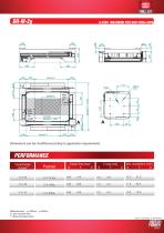
6 AXES MAXIMUM PAYLOAD 25KG+25KG Dimensions can be modified according to application requirements PERFORMANCE Travel Time (ms)* X Y Z Cycle/minute module** Reference travel x= 1000mm; y= 600mm (*) One way travel time (**) Back and forward travel
Open the catalog to page 13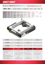
Direct Robot 8 AXES MAXIMUM PAYLOAD 7KG+7KG R0: clamped base moving tablescrew 00: no axis Hand Terminal D rive system S liding syste m Synchronous linear Maximum spe ed (m/ s ) Maximum a ccele rati on ( m / s ) 2 S t roke ra ng e (mm) P reven tive main ten anc e (*) Z axis lubrication must be executed at any X/Y axes greasing
Open the catalog to page 14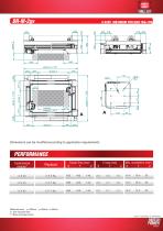
8 AXES MAXIMUM PAYLOAD 7KG+7KG Dimensions can be modified according to application requirements PERFORMANCE Travel Time (ms)* X Y Z Cycle/minute module** Reference travel x= 1000mm; y= 600mm; z=100mm (*) One way travel time (**) Back and forward travel
Open the catalog to page 15All Motor Power Company catalogs and technical brochures
 Mechatronics
12 Pages
 Galileo sphere
2 Pages
 Catalogue EPG planetary gearbox.
11 Pages
 Catalogue ROK worm-gearbox.
29 Pages
 DUET Catalogue
28 Pages
 Tetra Brushless Servomotor
60 Pages
 Catalogue for SKA Rotary.
28 Pages
 PENTA
PENTA36 Pages
 Motors
24 Pages
 Motioncontrol
32 Pages


Archived catalogs
 SKA_ROTARY
24 Pages
 Motioncontrol
8 Pages
 Mechatronics
8 Pages
 Power transmission
4 Pages
 Servo & Direct Drive
6 Pages
- AMOT electric motor
- AMOT DC motor
- Synchronous motor
- AMOT industrial robot
- Electric gearmotor
- AMOT servomotor
- AMOT rotary table
- AMOT permanent magnet motor
- Servo-amplifier
- Right angle electric gearmotor
- AMOT AC servomotor
- AMOT performance servomotor
- AMOT electric rotary table
- Motor-driven rotary table
- Multipole servomotor
- IP65 servomotor
- AMOT DC servomotor
- AMOT controller servomotor
- AMOT compact servomotor
- AMOT brushless servomotor