- Catalogs
- Motion Index Drives, Inc.
- XP Series
XP Series
1 /23Pages

XP Series
1 /23Pages
Catalog excerpts

XP Parallel Index Drives Rotary Indexer
Open the catalog to page 1
Application examples Direct driven belt/chain M = Mb + Mb Calculations J = moment of inertia *with one-sided lifting of loads Man = drive torque [Nm] j = friction coefficient g = acceleration of gravity = 9,81m/s2 R = radius m = mass [kg] a = switching angle [°] ts = index time [s] n = number of stops i = ratio P = drive power [kW] n = efficiency worm gear fa = drive speed [1/min] Indirect driven belt/chain M Transducer of rotations in horizontal movement M = M + M a becomes a’ b will be removed
Open the catalog to page 2
XP030 Dimensions The measurements shown here illustrate the standard unit. We will gladly customize the housing and or shaft(s) to suit your needs. The drive shaft as well as the output shaft are available as double sided shafts with and without a keyway. If you would like to add additional holes into the housing yourself, please contact us for possible drilling depths. A =Drive shaft Configuration of all parallel drives The dimensions for the gearmotor may change based on the gearmotor size and options required for the application.
Open the catalog to page 3
1) Parallel drives with stop numbers 6, 8 and 10 are designed as a double index, i.e. with each full rotation of the drive shaft, two indexes occur in the output. 2) Parallel drives with 12 stops are designed as a four step index, i.e. with each full rotation of the drive shaft, four indexes occur in the output. 3) The additional load occurring with chains and belts due to friction is not taken into consideration here and must be calculated separately. Main Dimensions Capacities Shaft distance [mm] 30 Weight without drive [kg] 0.7 Index angle [°] see Load Table (other index angles upon request)...
Open the catalog to page 4
XP040 Dimensions The measurements shown here illustrate the standard unit. We will gladly customize the housing and or shaft(s) to suit your needs. The drive shaft as well as the output shaft are available as double sided shafts with and without keyways. If you would like to add additional holes into the housing yourself, please contact us for possible drilling depths. A = Drive Shaft The dimensions for the gearmotor may change based on the gearmotor size and options required for the application.
Open the catalog to page 5
1) Parallel drives with stop numbers 6, 8 and 10 are designed as a double index, i.e. with each full rotation of the drive shaft, two indexes occur in the output. 2) Parallel drives with 12 stops are designed as a four step index, i.e. with each full rotation of the drive shaft, four indexes occur in the output. 3) The additional load occurring with chains and belts due to friction is not taken into consideration here and must be calculated separately. Max. Output torque Input Shaft Load rating dynamic [kN] Load rating static [kN] Output Shaft Load rating dynamic [kN] Load rating static [kN]...
Open the catalog to page 6
XP050 Dimensions The measurements shown here illustrate the standard unit. We will gladly customize the housing and or shaft(s) to suit your needs. The drive shaft as well as the output shaft are available as double sided shafts with and without keyways. If you would like to add additional holes into the housing yourself, please contact us for possible drilling depths. A = Drive Shaft The dimensions for the gearmotor may change based on the gearmotor size and options required for the application.
Open the catalog to page 7
1) Parallel drives with stop numbers 6, 8 and 10 are designed as a double index, i.e. with each full rotation of the drive shaft, two indexes occur in the output. 2) Parallel drives with 12 stops are designed as a four step index, i.e. with each full rotation of the drive shaft, four indexes occur in the output. 3) The additional load occurring with chains and belts due to friction is not taken into consideration here and must be calculated separately. Max. Output torque Input Shaft Load rating dynamic [kN] Load rating static [kN] Output Shaft Load rating dynamic [kN] Load rating static [kN]...
Open the catalog to page 8
XP065 Dimensions The measurements shown here illustrate the standard unit. We will gladly customize the housing and or shaft(s) to suit your needs. The drive shaft as well as the output shaft are available as double sided shafts with and without keyways. If you would like to add additional holes into the housing yourself, please contact us for possible drilling depths. A = Drive Shaft The dimensions for the gearmotor may change based on the gearmotor size and options required for the application.
Open the catalog to page 9
Load Table 1) Parallel drives with stop numbers 6, 8 and 10 are designed as a double index, i.e. with each full rotation of the drive shaft, two indexes occur in the output. 2) Parallel drives with 12 stops are designed as a four step index, i.e. with each full rotation of the drive shaft, four indexes occur in the output. 3) The additional load occurring with chains and belts due to friction is not taken into consideration here and must be calculated separately. Main Dimensions Capacities Shaft distance [mm] 63 Weight without drive [kg] 8 Index angle [°] see Load Table (other index angles upon...
Open the catalog to page 10
XP080 Dimensions The measurements shown here illustrate the standard unit. We will gladly customize the housing and or shaft(s) to suit your needs. The drive shaft as well as the output shaft are available as double sided shafts with and without keyways. If you would like to add additional holes into the housing yourself, please contact us for possible drilling depths. A = Drive Shaft The dimensions for the gearmotor may change based on the gearmotor size and options required for the application.
Open the catalog to page 11
1) Parallel drives with stop numbers 6, 8 and 10 are designed as a double index, i.e. with each full rotation of the drive shaft, two indexes occur in the output. 2) Parallel drives with 12 stops are designed as a four step index, i.e. with each full rotation of the drive shaft, four indexes occur in the output. 3) The additional load occurring with chains and belts due to friction is not taken into consideration here and must be calculated separately. Max. Output torque Input Shaft Load rating dynamic [kN] Load rating static [kN] Output Shaft Load rating dynamic [kN] Load rating static [kN]...
Open the catalog to page 12All Motion Index Drives, Inc. catalogs and technical brochures
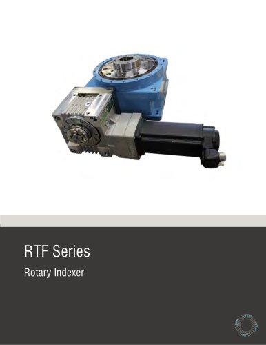 RTF Rotary Index Tables
13 Pages
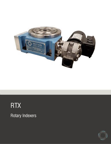 RTX Rotary Index Tables
20 Pages
 TSR Series
13 Pages
 TT315 Series
7 Pages
 RT Series Rotary Index Table
14 Pages
 Precision Link Conveyor
12 Pages
 Weld Positioner
5 Pages
 TMF Series Rotary Index Table
15 Pages
 Pick and Place
5 Pages
 Product Catalog
152 Pages
 MX150 Slip Ring Brochure
2 Pages
 MX470 Slip Ring Brochure
3 Pages
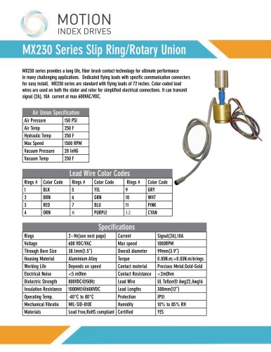 MX230 Slip Ring Brochure
2 Pages
- Rail conveyor
- Transport rail conveyor
- Horizontal conveyor
- Rotary joint
- Multi-port rotary union
- Electric drive conveyor
- Chain conveyor
- Work conveyor
- Oil rotary distributor
- Positioner
- Feed conveyor
- Transfer conveyor
- Conveyor for the pharmaceutical industry
- Mobile conveyor
- Rotary indexing table
- Flexible conveyor
- Assembly line conveyor
- Electric positioner
- Pick-and-place machine
- Electric rotary indexing table