- Catalogs
- Motion Index Drives, Inc.
- RTX Rotary Index Tables
RTX Rotary Index Tables
1 /20Pages
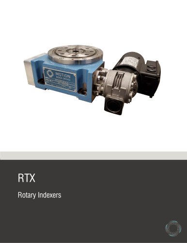
RTX Rotary Index Tables
1 /20Pages
Catalog excerpts
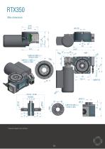
* Dimensions depend on the used drive
Open the catalog to page 2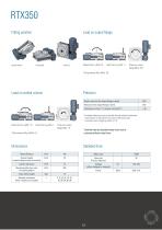
Fitting position Load on output flange Load on central column Torque on output flange [Nm] 10 Axial runout on the output flange 0 [mm] * Increased indexing accuracy accessible through selected components From division 16, the division error due to multi-point locks on the drive cam is larger by a factor of 1.5“ Combined loads and possible process forces must be confirmed by Motion Index Drives. Standard drive Motor size
Open the catalog to page 3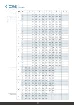
Load table RTX350 n = Number of stops / 360° revolution of output flange t = Step time in [s] JMax = Mass moment of inertia (base plate + fixtures and parts) in [Kgm2] Without motor and lifetime JL = Mass moment of inertia by life time (base plate + fixtures and parts) in [Kgm2] J = Mass moment of inertia with motor (base plate + fixtures and parts) in [Kgm2] From n=16 The output flange steps 2 times per cam revolution From n=36 The output flange steps 3 times per cam revolution
Open the catalog to page 4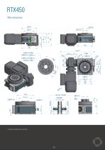
* Dimensions depend on the used drive
Open the catalog to page 5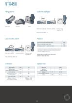
Fitting position Load on output flange Radial force F,a [N] 17.5 Axial force F3a [kN] 20 Torque on output flange [Nm] 322 Load on central column Precision Axial runout on the output flange 0 [mm] * Increased indexing accuracy accessible through selected components From division 16, the division error due to multi-point locks on the drive cam is larger by a factor of 1.5“ Axial force FaM [kN] 18 Torque on output flange [Nm] 77 Combined loads and possible process forces must be confirmed by Motion Index Drives. Standard drive Output flange 0 Motor size
Open the catalog to page 6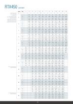
Load table RTX450 n = Number of stops / 360° revolution of output flange t = Step time in [s] JMax = Mass moment of inertia (base plate + fixtures and parts) in [Kgm2] Without motor and lifetime JL = Mass moment of inertia by life time (base plate + fixtures and parts) in [Kgm2] J = Mass moment of inertia with motor (base plate + fixtures and parts) in [Kgm2] From n=16 The output flange steps 2 times per cam revolution From n=36 The output flange steps 3 times per cam revolution
Open the catalog to page 7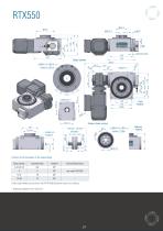
Position of the hole pattern in the output flange Stop number Further stop numbers you can find in the RTF/RTX550 dimension sheet at our website. * Dimensions depend on the used drive
Open the catalog to page 8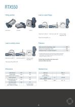
Fitting position Load on output flange Radial force FrA [kN] 23 Axial force FaA [N] 18.4 Torque on output Precision Axial runout on the output flange 0 [mm] * Increased indexing accuracy accessible through selected components From division 16, the division error due to multi-point locks on the drive cam is larger by a factor of 1.5“ Axial force FaM [kN] 18 Torque on output flange [Nm] 77 Combined loads and possible process forces must be confirmed by Motion Index Drives. Standard drive Output flange 0 Motor size
Open the catalog to page 9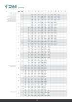
Load table RTX550 n = Number of stops / 360° revolution of output flange t = Step time in [s] JMax = Mass moment of inertia (base plate + fixtures and parts) in [Kgm2] Without motor and lifetime JL = Mass moment of inertia by life time (base plate + fixtures and parts) in [Kgm2] J = Mass moment of inertia with motor (base plate + fixtures and parts) in [Kgm2] From n=16 The output flange steps 2 times per cam revolution From n=36 The output flange steps 3 times per cam revolution
Open the catalog to page 10
Fitting position Load on output flange Radial force FrA [kN] 20 Axial force FaA [kN] 22.5 Torque on Precision Axial runout on the output flange 0 [mm] * Increased indexing accuracy accessible through selected components From division 16, the division error due to multi-point locks on the drive cam is larger by a factor of 1.5“ Axial force FaM [kN] 14 Torque on output flange [Nm] 170 Combined loads and possible process forces must be confirmed by Motion Index Drives. Standard drive Output flange 0 Motor size
Open the catalog to page 12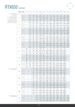
Load table n = Number of stops / 360° revolution of output flange t = Step time in [s] JMax = Mass moment of inertia (base plate + fixtures and parts) in [Kgm2] Without motor and lifetime JL = Mass moment of inertia by life time (base plate + fixtures and parts) in [Kgm2] J = Mass moment of inertia with motor (base plate + fixtures and parts) in [Kgm2] From n=16 The output flange steps 2 times per cam revolution From n=36 The output flange steps 3 times per cam revolution
Open the catalog to page 13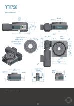
* Dimensions depend on the used drive
Open the catalog to page 14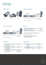
Fitting position Load on output flange Load on central column Axial runout on the output flange 0 [mm] Radial force FrM [kN] 3.8 Axial force FaM [kN] 15 Torque on output * Increased indexing accuracy accessible through selected components From division 16, the division error due to multi-point locks on the drive cam is larger by a factor of 1.5" Standard drive Motor size
Open the catalog to page 15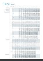
Load table RTX750 n = Number of stops / 360° revolution of output flange t = Step time in [s] JMax = Mass moment of inertia (base plate + fixtures and parts) in [Kgm2] Without motor and lifetime JL = Mass moment of inertia by life time (base plate + fixtures and parts) in [Kgm2] J = Mass moment of inertia with motor (base plate + fixtures and parts) in [Kgm2] From n=16 The output flange steps 2 times per cam revolution From n=36 The output flange steps 3 times per cam revolution
Open the catalog to page 16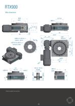
* Dimensions depend on the used drive
Open the catalog to page 17
Fitting position Load on output flange Load on central column Axial runout on the output flange 0 [mm] * Increased indexing accuracy accessible through selected components From division 16, the division error due to multi-point locks on the drive cam is larger by a factor of 1.5“ Axial force FaM [kN] 25 Torque on output flange [Nm] 450 Combined loads and possible process forces must be confirmed by Motion Index Drives. Standard drive Output flange 0 Motor size
Open the catalog to page 18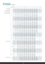
Load table RTX900 n = Number of stops / 360° revolution of output flange t = Step time in [s] JMax = Mass moment of inertia (base plate + fixtures and parts) in [Kgm2] Without motor and lifetime JL = Mass moment of inertia by life time (base plate + fixtures and parts) in [Kgm2] J = Mass moment of inertia with motor (base plate + fixtures and parts) in [Kgm2] From n=16 The output flange steps 2 times per cam revolution From n=36 The output flange steps 3 times per cam revolution
Open the catalog to page 19All Motion Index Drives, Inc. catalogs and technical brochures
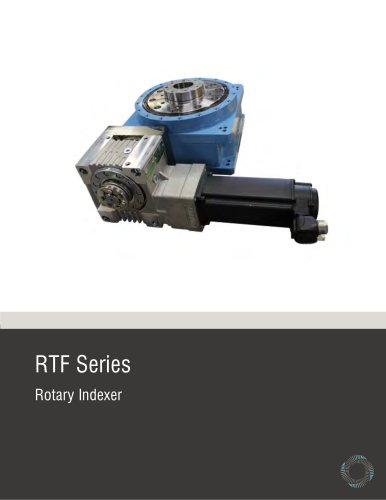 RTF Rotary Index Tables
13 Pages
 TSR Series
13 Pages
 TT315 Series
7 Pages
 RT Series Rotary Index Table
14 Pages
 Precision Link Conveyor
12 Pages
 Weld Positioner
5 Pages
 TMF Series Rotary Index Table
15 Pages
 XP Series
23 Pages
 Pick and Place
5 Pages
 Product Catalog
152 Pages
 MX150 Slip Ring Brochure
2 Pages
 MX470 Slip Ring Brochure
3 Pages
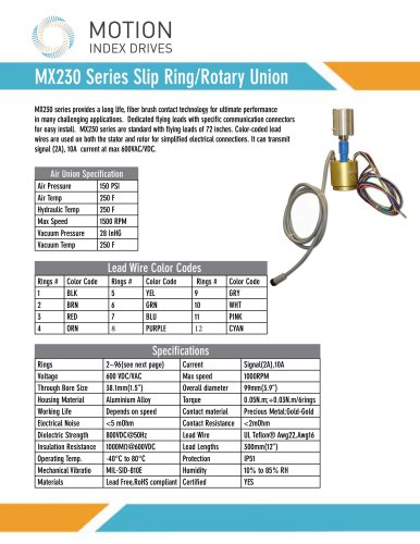 MX230 Slip Ring Brochure
2 Pages
- Rail conveyor
- Transport rail conveyor
- Horizontal conveyor
- Rotary joint
- Multi-port rotary union
- Electric drive conveyor
- Chain conveyor
- Work conveyor
- Oil rotary distributor
- Positioner
- Feed conveyor
- Transfer conveyor
- Conveyor for the pharmaceutical industry
- Mobile conveyor
- Rotary indexing table
- Flexible conveyor
- Assembly line conveyor
- Electric positioner
- Pick-and-place machine
- Electric rotary indexing table