- Catalogs
- Moteck Electric Corp
- Actuator MK35
Actuator MK35
1 /5Pages

Actuator MK35
1 /5Pages
Catalog excerpts

Product Data Sheet Actuator MK35 MK35 is an intelligent actuator with PCBA control board inside. Its robust mechanical design can provide up to 10,000N thrust, and meets IP69K waterproof protection. The built-in control circuit board has the protection function of monitoring current and voltage, and there are different control version options to suit the user's master system. MK35 is truly a favorable choice for applications such as agriculture, construction and industrial automation. Main applications: Agriculture, Construction and Industrial Automation. Input voltage: 24V DC Max. load: 10,000N (Push/Pull) Max. static load: 18,000N (Push) Max. speed at no load: 40mm/sec (typical value) Speed at full load: 8mm/sec (typical value @10,000N loaded) Stroke: 100 ~ 1,000mm (the max. stroke is depending on load, refer to Dimensions) Manual drive capable by an hexagon socket wrench Stainless steel extension tube IP level: IP66 (dynamic) and IP67/IP69K (static) Built-in stroke limit switches Different control version options to suit the user’s master system Operating voltage and current monitoring and protection Soft start / stop Duty cycle: 15 ~ 25%. Refer to Performance Data Operating ambient temperature: -40°C ~ +80°C (
Open the catalog to page 1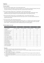
Options Control options ● S0L Control options: Signal control + End of stroke signal output The S0L uses low current signal to control the actuator move or stop without switching the polarity of the input DC power, and there is an arrival signal output when it reaches the end of stroke (EoS). ● SPL Control options: Signal control + Potentiometer + End of stroke signal output In addition to having all the same features as S0L, the SPL option also provides a potentiometer output, allowing the user's control equipment to know the absolute position of the actuator at any time. ● SHL Control options:...
Open the catalog to page 2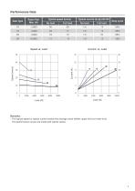
Performance Data *Typical speed (mm/s) Gear type Full load Full load Duty cycle Remarks: * The typical speed or typical current means the average value neither upper limit nor lower limit. The performance curves are made with typical values.
Open the catalog to page 3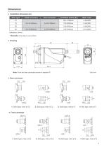
Dimensions ● Installation dimension (A) Slot connector Solid connector Gear type * Remarks: One step in every 50mm ● Drawing Note: Front and rear connectors shown in standard 0° 1: Solid type, hole ø12.2 2: Slot type, hole ø12.2 3: Solid type, hole ø13 4: Slot type, hole ø13 1: Solid type, hole ø12.2 2: Slot type, hole ø12.2
Open the catalog to page 4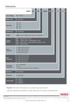
Input voltage Control options S0L*:Signal control + EoS SPL*:Signal control + Potentiometer + EoS SHL:Signal control + Dual Hall effect sensors + EoS J00:J1939 CAN Bus Front connector Rear connector Connector orientation 0:0° (standard) 9:90° (Front and rear connectors shown in standard 0°) Cable length B:Ball Screw Spindle type Gear type Motor code * Remarks: S0L and SPL control options are only available for gear ratios 20 and 30. More information about installation and usage, please refer to User Guide or contact Moteck sales. Terms of Use The user is responsible for the suitability of MOTECK...
Open the catalog to page 5All Moteck Electric Corp catalogs and technical brochures
 Wireless Control TXH
5 Pages
 Actuator LD3
14 Pages
 Actuator FD60
8 Pages
 CF16
CF164 Pages
 BD62
BD627 Pages
 Moteck_Actuator_2017
60 Pages
 Moteck_Twinmat Series
6 Pages
 Motorized Medical Actuator
6 Pages
 Moteck_Furniture_Actuator
6 Pages
 Gate Opener Catalogue
9 Pages
 2014-2015 CATALOGUE
4 Pages


- Linear actuator
- Electric actuator
- Wireless remote control
- Industrial remote control
- Remote control with buttons
- Compact actuator
- Industrial actuator
- DC actuator
- 24-volt actuator
- Motorized actuator
- Stainless steel actuator
- 12-volt actuator
- Standard actuator
- Actuator for medical applications
- Corded remote control
- IP54 actuator
- 8-button remote control
- Mechanical actuator
- IP66 actuator