TRD8
1 /12Pages
TRD8
1 /12Pages
Catalog excerpts

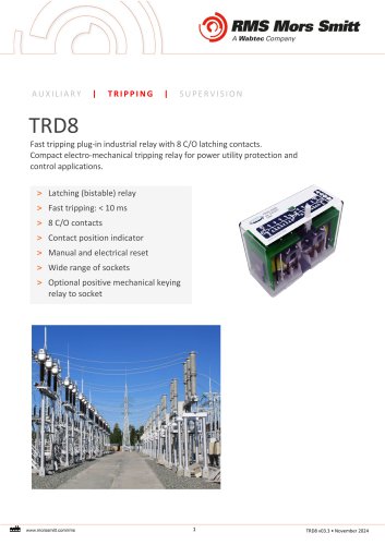
AUXILIARY | TRIPPING | SUPERVISION Fast tripping plug-in industrial relay with 8 C/O latching contacts. Compact electro-mechanical tripping relay for power utility protection and control applications. > Latching (bistable) relay > Contact position indicator > Manual and electrical reset > Wide range of sockets > Optional positive mechanical keying relay to socket
Open the catalog to page 1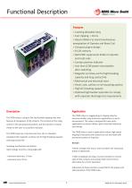
Features > Latching (bistable) relay > Reset inhibitor to avoid simultaneous energization of Operate and Reset Coil > Compact plug-in design > Back EMF suppression diode on operate and reset coils > Contact position indicator > Less than 0.2W power consumption after switching > Magnetic arc blow-out for high breaking capacity and long contact life > Mechanical and electrical reset > Panel, rack, surface or rail mounting options > High DC breaking capacity > Optional high burden operation to comply with capacitor discharge test requirements The TRD8 relay is a plug-in fast trip bistable tripping...
Open the catalog to page 2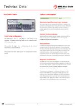
Technical Data Front Panel Layout Contact Configuration Latching contacts Mechanical and Electrical Reset Contacts All contacts operate and mechanically latch when a voltage in the specified range is applied to the relay coil. The contacts reset when the reset button located on the front of the relay is pressed. A voltage applied to the reset coil may also be used to reset the contacts. Contact Position Indicator Front Panel Configuration Operate and reset position indicator displays current state of the relay. Pressing manual push button will reset the relay and changes the indicator position...
Open the catalog to page 3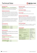
Make contacts < 10 ms (at Rated Voltage) *All Speeds are first touch excluding bounce time. Above data is only for electrical set and reset at nominal rated operating voltage. The TRD8 tripping relay is designed for high burden operation, making it suitable for application in high-security circuit breaker tripping circuits, particularly where the initiating contact may be located remotely from the relay. The high burden configuration of the TRD8 relay also facilitates the satisfactory operation of external series elements. This high burden design provides the TRD8 relay with maximum immunity...
Open the catalog to page 4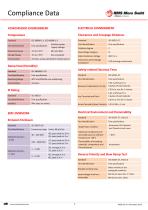
Compliance DataATMOSPHERIC ENVIRONMENT TemperatureELECTRICAL ENVIRONMENT Clearances and Creepage Distances Standard Damp Heat (Humidity) rrrr. www.morssmitt.com/rms
Open the catalog to page 5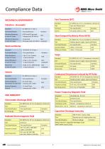
Compliance Data Standard MECHANICAL ENVIRONMENT Vibration - Sinusoidal Standard Capacitive Discharge Immunity Radiated Electromagnetic Field rrrr. www.morssmitt.com/rms
Open the catalog to page 6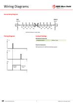
Wiring Diagrams Connectiong Diagram Timing Diagram Contact RatingsMechanical endurance Unloaded contact 1 Million Cycles 50K operations for defined breaking capacity
Open the catalog to page 7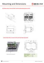
Surface Mount Rear Connect B-V87 with Flush Mounting Socket PANEL THICKNESS (T) rrrr. www.morssmitt.com/rms
Open the catalog to page 8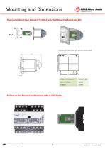
rrrr. www.morssmitt.com/rms
Open the catalog to page 9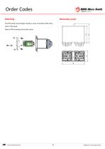
'0)1 RMS Mors Smitt 4 Wabtec Company Mounting The V87 panel mount design includes a cover to maintain IP4X at the front of the panel. Relay is IP4X at product level with socket.
Open the catalog to page 10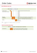
Delta TRD8 Relay Order Code TRD8 - Nominal Operate Voltage Plug in relay only (no terminal block or mounting hardware) Surface or rail mounting including V93 terminal block Panel mount - V87 term block, retention bracket and cover None High Burden NOTE 1 The TRD8 relay will be supplied for mounting as per the order code specified. Delta Terminal Block Order Codes V87 - Socket - Surface/panel mount - 28 terminals
Open the catalog to page 11
This safety section should be read before commencing any work on the equipment The information in the safety section of the product documentation is intended to ensure that products are properly installed and handled in order to maintain them in a safe condition. It is assumed that everyone who will be associated with the equipment will be familiar with the contents of the safety section. Explanation of Symbols & Labels The meaning of symbols and labels which may be used on the equipment or in the product documentation is given below. Caution: Refer to product information Caution: Risk of electric...
Open the catalog to page 12All Mors Smitt BV catalogs and technical brochures
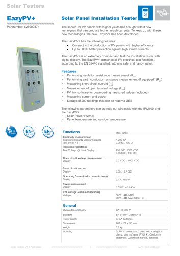 EazyPV+
1 Page
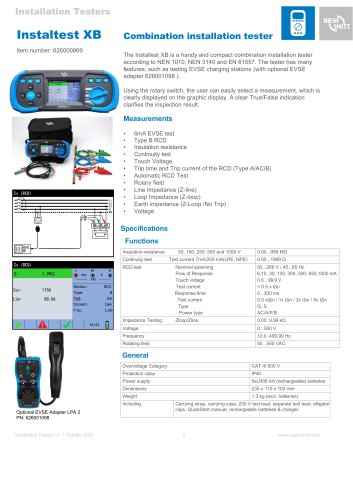 Instaltest XB
1 Page
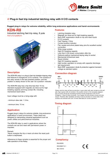 KDN-R8
14 Pages
 V88 Socket
9 Pages
 V33
V338 Pages
 Universal relays
12 Pages
 Products & services
16 Pages
 Signalling & rail infrastructure
20 Pages
 Activities brochure
12 Pages
 Relay Life Services brochure
8 Pages
 Mors Smitt Group
19 Pages
 Instruments 2
46 Pages
 Instruments 1
74 Pages
 Substation protection & control
12 Pages
 SPD - Surge Protection Devices
60 Pages
 brochure Railway activity
16 Pages
 Protection components
20 Pages
 Railway Technology
11 Pages
 Brochure Mors Smitt Goup
13 Pages
 Signalling relays BR930
11 Pages
 Brochure Door control units
11 Pages
 Brochure Protection components
11 Pages
 Miniature circuit breakers
17 Pages
 Mors Smitt Railway relays brochure
196 Pages
 Engineered solutions
32 Pages
 Mors Smitt Heavy Duty Relays
100 Pages
 Mors Smitt Industrial Technology
24 Pages
 Mors Smitt Products & Services
12 Pages


- Switching relay
- Portable tester
- Portable analyzer
- Protection relay
- Digital tester
- Automatic tester
- Industrial tester
- Electromechanical relay
- Voltage testing system
- Time relay
- DC electromechanical relay
- Power quality analyzer
- Insulation testing system
- Cabling tester
- Compact tester
- Monitoring relay
- Current protection relay
- Continuity tester
- Electrical network analyzer