
- Catalogs
- Mors Smitt BV
- Mors Smitt Railway relays brochure

Mors Smitt Railway relays brochure

Mors Smitt Railway relays brochure
- D-platform: Compact multifunctional relays with up to 4 change-over contacts.
- A/B-platform: Heavy-duty relays with long mechanical life, suitable for various applications.
- CU-platform: Small relays with up to 2 change-over contacts.
- C-platform: Flat multifunctional relays with up to 9 change-over contacts.
- Specials: Relays with diverse functionalities for different applications.
- Mechanical Life: Ranges from 2 x 10⁶ to 50 x 106 operations depending on the relay type.
- Weight: Typically 140 g, with some models weighing up to 305 g.
- Operating Temperature: Standard range is -25 °C to +70 °C, with options for low temperature operation down to -40 °C or -50 °C.
- Humidity: Up to 95% with temporary condensation permitted.
- Types of Contacts: Available in configurations such as 2 C/O, 3 C/O + 1 N/C, 4 C/O, and 8 C/O.
- Current Ratings: Maximum make current of 16 A, with continuous current ratings up to 10 A.
- Switching Voltage: Maximum of 250 VDC or 440 VAC.
- Contact Resistance: Initial resistance is 15 mΩ.
- Low temperature operation, gold plated contacts, special dust protection, LED coil indicator, and various diode configurations.
- Magnetic arc blow-out and high resistance to welding with AgSnO2 contacts.
- Push-to-test button and double make/break options.
- AC Coil Relays: Suitable for AC coil voltages with a frequency of 50/60 Hz, featuring high DC breaking capacity and optional mechanical keying.
- Bistable Relays: Latching relays with contacts that remain in the last powered position, featuring a clear position indicator.
- Timer Relays: Electronic railway timer relays with adjustable delay on pull-in, featuring weld-no-transfer contacts.
- Time Delay Functions: Available in delay on pull-in, delay on drop-out, and combinations of both. Adjustable time ranges from 0.1 seconds to 60 minutes.
- Contact Configurations: Options include 1 C/O + 1 N/O, 2 C/O, 3 C/O, and 4 C/O contacts, with maximum make currents ranging from 6 A to 16 A.
- Voltage Ratings: Nominal voltages range from 24 VDC to 240 VDC, with specific models supporting AC input voltages.
- Mechanical and Environmental Characteristics: Operating temperature range is -25°C to +70°C, with humidity tolerance up to 93%.
- Compact plug-in design with integrated snap-lock and optional positive mechanical keying relay to socket.
- Adjustable delay times with lockable knobs and status indication via LEDs.
- Magnetic arc blow-out and weld-no-transfer contacts for enhanced reliability.
- Wide range of sockets available for versatile mounting options.
- Low temperature operation (-40°C).
- Gold plated contacts and extra dust protection.
- Double zener diode over input for enhanced protection.
The document outlines various types of plug-in railway relays with different specifications. Key specifications include nominal voltage, time delay functions, contact types, and current ratings. The relays are designed for both DC and AC applications with adjustable time ranges and voltage monitoring capabilities.
Contact and Current Specifications:
Relays are available with 2 or 4 change-over (C/O) contacts. Maximum make current ranges from 10 A to 16 A, with peak inrush current up to 200 A. Maximum continuous current is specified at 8 A to 10 A, and maximum switching voltage varies between 250 VDC and 440 VAC. Minimum switching voltage is 12 V, and minimum switching current is 10 mA.
Mechanical and Environmental Characteristics:
The relays have a mechanical life expectancy of up to 30 million operations and can operate within a temperature range of -25 °C to +70 °C. They are designed to withstand humidity levels up to 95%, with some models allowing temporary condensation.
Voltage Monitoring and Timing Functions:
The relays include features such as voltage monitoring, adjustable pull-in voltage, and hysteresis. Timing functions include delay on pull-in and flashing with symmetrical pulse rates. Adjustable time ranges are provided for various applications.
Options and Additional Features:
Optional features include low-temperature operation, gold-plated contacts, special dust protection, and magnetic arc blow-out. Some models offer integrated snap-locks and positive mechanical keying for secure socket connections.
Applications:
These relays are suitable for railway applications, offering high DC breaking capacity and robust design for reliable performance in demanding environments. They are available in compact plug-in designs with a wide range of sockets.
- FDA4 Series: Features symmetrical flashing with 4 change-over (C/O) contacts, a fixed pulse rate, and options for adjustable pulse rates. It supports a maximum make current of 16 A and a continuous current of 10 A.
- FDC Series: Offers asymmetrical flashing with 2 C/O contacts, fixed pulse and interval times, and options for magnetic arc blow-out and dust protection.
- FDG Series: Provides symmetrical flashing with solid-state contacts in counterphase, supporting a maximum switching capacity of 2 lamps of 84 W.
- WDE4 Series: Includes one-shot time relays with 4 C/O contacts, adjustable pulse times, and options for AC input voltages.
- PDF3 Series: Features one-shot relays with 3 C/O contacts, activated by the negative edge of DC voltage, with fixed pulse times.
- WDDE Series: Combines instantaneous and one-shot functions with 2 C/O instantaneous and 2 C/O one-shot contacts, suitable for both DC and AC inputs.
- Operating temperature ranges from -25°C to +70°C.
- Humidity tolerance varies between 80% and 95% depending on the model.
- Mechanical life expectancy ranges from 10 million to 30 million operations.
- Low temperature operation (-40°C).
- Gold plated contacts for enhanced conductivity.
- Extra dust protection and non-weldable contacts.
- Integrated snap-lock and optional positive mechanical keying relay to socket.
The document provides detailed specifications for various relay models, including mechanical life expectancy, weight, operating temperature, and humidity tolerance. For instance, the mechanical life is specified as 10 million operations, and the operating temperature range is -25 °C to +70 °C. The document also lists the dimensions and mounting possibilities for different relay types.
Ordering Scheme:
An example ordering scheme is provided for the D-platform relays, detailing the relay model, coil voltage, and available options such as low temperature operation, gold plated contacts, and special dust protection.
Electrical Life Expectancy:
The document includes graphs showing the AC and DC current breaking capacity versus life expectancy in millions of cycles. These graphs illustrate the performance of the relays under different load conditions and contact opening rates.
Sockets and Mounting:
Various socket types are described for different mounting possibilities, including surface/wall, rail, panel/flush, and PCB mounting. The document emphasizes the reliability and long-term availability of these sockets.
Design Features:
The A-/B-platform relays are highlighted for their design features, such as silver tin oxide contacts for welding resistance, self-cleaning contacts, and a safety design counter blade system. The relays are designed for safety-critical applications with features like double arc extinction and flexible coupling to extend mechanical life.
Options:
Several optional features are available for the relays, including gold-plated contacts, weld-no-transfer contacts, back EMF protection diodes, LED indicators, and manual reset control levers.
Contact Data:
Detailed contact data is provided, including maximum contact ratings, contact material, and resistance. The document specifies the electrical life expectancy and mechanical life of the contacts.
Additional Information:
The document references additional resources and datasheets available on the Morssmitt website for further detailed information.
- Mechanical Life: Over 100 million cycles.
- Weight: 300g to 450g depending on the model.
- Operating Temperature: -40°C to +80°C.
- Humidity Resistance: 93% RH at 40°C for 4 days.
- Maximum Continuous Current: 8A to 12A.
- Contact Overload Withstand: At 24 VDC, 10 x 100A to 200A for 10 ms, 1 operation per minute.
- Contact Material: Options include tin silver oxide and gold plating over hard silver.
- Contact Configuration: 4 double make/break C/O contacts (form Z).
- Nominal Voltage & Keying: Various models with VDC and VAC options, including AG, FL, DG, BG, SV, EG, SZ, CG, etc.
- Coil Resistance Tolerance: ±8% at 20°C.
- Protection Options: Transil coil protection, avalanche diode coil protection, LED voltage indicator, and relay cover for wire locking spring.
- Plug-in Design: Facilitates easy installation and maintenance.
- Secure Locking Feature: Ensures maximum ease of maintenance.
- Weld-No-Transfer Contacts: Available for safety-critical applications.
- Transil coil protection.
- Avalanche diode coil protection.
- LED voltage indicator.
- Relay cover for wire locking spring.
1. Contact Ratings:
- Operating: 20 mA maximum at 72 VDC
- Carry only: 5 A maximum at 5 VDC
- Minimum current: 1 mA at 12 VDC
- Stationary contacts: Solid gold alloy
- Moveable contacts: Gold over hard silver overlay laminated to copper
- < 20 mΩ at 5 A (carry only)
1. Plug-in Railway Relay:
- 3 silver double make/double break C/O contacts
- 1 gold bifurcated C/O contact
- Weld-no-transfer function for silver contacts
- Contact life (mechanical): 100 million cycles
- Secure locking feature for maintenance
- 2 stable magnetic latched states
- 4 C/O contacts for type 400, 3 C/O contacts for type 300
- Weld-no-transfer contacts optional
- Contact life (mechanical): 100 million cycles
1. Operating Temperature: -40 °C to +80 °C
2. Humidity: 93% RH at 40 °C for 4 days
3. Weight: 450 g
1. Nominal Voltage & Keying:
- Various models with different voltage ratings (e.g., AK 24 VDC, CK 36 VDC)
1. 400 Contact Type:
- Operates with a 50 ms pulse
- Magnetically latches contacts between positions
- Designed for permanent voltage actuation
- Magnetically latches contacts between positions
1. Options:
- Transil coil protection
- Avalanche diode coil protection
- LED voltage indicator
- Relay cover for wire locking spring
1. Delay-on Pull-in:
- Fixed time delay < 10 s
- Fixed time delay < 10 s
- Time delay programmable by dip switch
- Status LED indicator
- Nominal Voltage & Keying: Various models with nominal voltages ranging from 12 VDC to 110 VDC, with operating voltages and coil resistances specified for each model.
- Time Delay Function: The relays offer delay on pull-in or drop-out, selectable via a dip switch. The total time delay range varies from 0.25 seconds to 255 hours, depending on the model.
- Contact Data: Each relay features 4 double make/double break contacts (form Z) made of hard silver overlay laminated to copper. Initial contact resistance is 10 mΩ max at 5 A, increasing to 40 mΩ max at end of life.
- Mechanical & Environmental Characteristics: The relays have a mechanical life expectancy of over 100 million operations, can operate in temperatures from -40°C to +85°C, and withstand humidity levels of 93% RH at 40°C for 4 days.
- Compact plug-in design for easy installation and maintenance.
- Programmable time delay via dip switch, with a status LED indicator for operational status.
- Secure locking feature to ensure stability during operation.
- Weld-no-transfer contacts standard for enhanced reliability.
- Features a compact plug-in design with 6 A capacity and 4 change-over contacts (2 instantaneous and 2 delayed).
- Time delay is programmable via a dip switch, with a range of 0.5 to 60 seconds.
- Includes a status LED indicator and secure locking for maintenance.
- Operates within a temperature range of -40°C to +85°C and has a mechanical life of 10 million operations.
- Designed for delay on pull-in or drop-out with 8 A capacity and 4 double make/break contacts.
- Time delay is adjustable via a dip switch, ranging from 0.25 hours to 63.75 minutes.
- Features a status LED and a mechanical life of over 100 million cycles.
- Similar to TPBAU 400 but triggered by the negative edge of the command input.
- Maintains the same time delay range and mechanical characteristics.
- Supports a higher current capacity of 12 A with similar features to TPBAU 400.
- Contact overload withstands up to 200 A at 24 VDC for 10 ms.
- Provides delay on both pull-in and drop-out with 8 A capacity.
- Time delay is programmable, with a range from 0.25 seconds to 63.75 minutes.
- Monitors current levels from 16 A to 24 A with 2 change-over contacts.
- Features adjustable current measurement and a maximum shunt current of 40 A.
- Designed for load shedding based on battery voltage levels with delay-on and delay-off functions.
- UB 001 has 1 N/O solid state contact, while UB 002 has 2 N/O contacts.
- Both models operate within a voltage range of 24 VDC to 110 VDC.
- All relays feature a compact plug-in design with secure locking for maintenance.
- Operating temperature range is typically -40°C to +85°C.
- Mechanical life expectancy is generally over 100 million operations for most models.
- Voltage Monitoring Relays: These relays are designed to open auxiliary load circuits when battery voltage drops too low and restore them when the voltage recovers. They feature a compact plug-in design, secure locking, and are available with different configurations of normally open (N/O) and changeover (C/O) contacts.
- Flashing Relays: These relays provide symmetrical and asymmetrical flashing functions with adjustable pulse and interval times. They are equipped with double make/break contacts and status LED indicators.
- Time delay on voltage increase: 0 to 20 seconds (adjustable on request).
- Time delay on voltage drop: 0 to 20 seconds (adjustable on request).
- Operating voltage range: 24 VDC to 110 VDC.
- Operating current: Less than 10 mA to 50 mA depending on the model.
- Maximum load current: Ranges from 0.2 A to 12 A.
- Operating temperature: -40 °C to +85 °C.
- Weight: Varies from 150 g to 450 g.
- Humidity tolerance: 93% RH at 40 °C for 4 days.
- Coil Protection: Options include no protection, avalanche diode, and Transil protection (specific to 400 type).
- Contact Types: Regular double break contacts and weld-no-transfer options are available.
- LED Indicators: Relays can be equipped with or without LED voltage indicators.
- Mechanical Life: Exceeds 100 million operations.
- Operating Conditions: Temperature range from -40°C to +80°C, with humidity tolerance of 93% RH at 40°C for 4 days.
- Electrical Life Expectancy: Detailed through dynamic relay selection curves, showing AC and DC current breaking capacities versus life expectancy in millions of cycles.
- Current Breaking Capacity: Curves illustrate the relationship between current, voltage, and life expectancy for both resistive and inductive loads.
- Load Time Constant (L/R): Maximum power interruption data is provided for various load time constants and voltages.
- Each relay type has a specific ordering scheme, with detailed dimensions and mounting possibilities available on the Mors Smitt website.
- Dimensions are provided for various relay types, with options for locking brackets and wire locking springs.
- Connecting two contacts in series increases DC current breaking capacity by 50%.
- Curves are provided for both resistive (Power Factor = 1) and inductive loads, with specific attention to continuous current and load time constants.
The document outlines the specifications for various relay models, focusing on their electrical and mechanical characteristics. Key specifications include:
- Continuous current and DC current breaking capacity, which can be increased by 50% by connecting two contacts in series.
- Life expectancy of 800,000 cycles for certain models.
- Maximum contact breaking capacity versus voltage for different L/R values.
- AC current breaking capacity versus life expectancy in millions of cycles.
The document provides guidelines for mounting and connecting relay sockets. It details:
- Surface/wall mounting and panel/flush mounting options.
- Various connection terminals and their specifications.
- Instructions for mounting on a 35 mm rail by adding a suffix D.
The relays are designed to be corrosion-resistant, shock and vibration-resistant, and suitable for hazardous areas. They feature a safety design counter blade system to ensure they remain in a logical configuration, which is crucial for safety-critical applications.
The document recommends using gold-plated contacts for environments with corrosive atmospheres and for switching low currents and voltages. It also suggests positive mechanical keying to prevent incorrect relay insertion.
The document includes several curves and tables illustrating:
- Maximum power interruption versus load time constant (L/R) for given voltages.
- Electrical life expectancy and maximum switching capacity for different relay models.
- Nominal, minimum, and maximum voltages, along with coil resistance for various relay types.
Relays are available in different models with specific features such as:
- Miniature design with high contact life and optional features like gold-plated contacts.
- Different contact arrangements and coil voltages.
- Mechanical life expectancy ranging from 10 to 30 million operations.
- Contact Type: 1 double make/double break contact.
- Maximum Make Current: 15 A.
- Maximum Continuous Current: 8 A.
- Maximum Switching Voltage: 300 VDC (max current 300 mA), 250 VAC (max current 2.6 A).
- Minimum Switching Voltage: 12 V.
- Minimum Switching Current: 10 mA.
- Contact Resistance: Maximum 15 mΩ.
- Material: Silver with 0.2 µm gold flash for storage purposes.
- Mechanical Life: 30 million operations.
- Operating Temperature: -40 °C to +70 °C.
- Humidity: 95% (temporary condensation permitted).
- Weight: 40 g.
- Relays feature up to 9 change-over contacts with a mechanical life of 100 million cycles.
- Standard base dimensions are 33 x 65 mm.
- Maximum continuous current is 8 A with contact overload withstand at 24 VDC: 10 x 160 A for 10 ms.
- Operating temperature range is -40 °C to +80 °C with humidity tolerance of 93% RH at 40 °C for 4 days.
- Options include silver tin oxide contacts for welding resistance and gold contacts for dry circuit applications.
- Self-cleaning contacts and a safety design counter blade system ensure reliability in safety-critical applications.
- Double arc extinction and double make/break contacts enhance electrical life and performance under high inductive or capacitive loads.
- Gold-plated contacts for resistance against corrosive atmospheres.
- Weld-no-transfer contacts ensure that N/C and N/O contacts cannot be closed simultaneously.
- Back EMF protection diode and LED indicators for power supply status.
- Double zener coil protection diode for surge protection.
- Mechanical keying to prevent incorrect relay insertion.
- Contact material includes hard silver overlay laminated to copper and gold plating for specific applications.
- Initial contact resistance is 10 mΩ max at 5 A, increasing to 40 mΩ max at end of life.
- Electrical life expectancy is detailed in curves provided in the document.
- Relays are designed for plug-in installation with secure locking features for ease of maintenance.
- Weight is approximately 400 g.
- Contact Material: Hard silver overlay laminated to copper.
- Contact Resistance: Initial 10 mΩ max at 5 A; end of life 40 mΩ max at 5 A.
- Electrical Life Expectancy: Refer to curves on page 146.
- Operating Temperature: -40 °C to +85 °C for latching relays; -25 °C to +70 °C for flashing relays.
- Latching Relay Operation: Utilizes two separate coils and a magnetic rocker mechanism. A pulse of 50 ms minimum duration is required to actuate the relay.
- Voltage Monitoring Relay: Activates when input voltage exceeds the control threshold, with a predefined activation time.
- Flashing Relay: Controls filament lightbulbs with factory-set independent output channels and flashing delay.
- Coil Resistance Tolerance: ± 8% at 20 °C.
- Contact Life: Mechanical life of 50 million cycles.
- Secure Locking Feature: Ensures ease of maintenance.
- Timing and Connection Diagrams: Provided for different relay operations.
- Electrical Life Expectancy Curves: Show AC and DC current breaking capacity versus life expectancy in millions of cycles, with specific curves for resistive and inductive loads.
- Nominal Voltage and Coil Resistance: Various models are listed with nominal voltages ranging from 12 VDC to 115 VDC, with coil resistance tolerances of ±8% at 20°C.
- Mechanical Life: The relays have a mechanical life expectancy ranging from 10 million to 100 million operations, depending on the model.
- Operating Temperature: The relays can operate in temperatures ranging from -50°C to +80°C.
- Humidity: The relays can withstand humidity levels up to 95% RH, with some models allowing temporary condensation.
- Contact Material: Contacts are made from hard silver or silver tin oxide, with some models featuring gold flash for storage purposes.
- Contact Resistance: Initial contact resistance is typically 10 mΩ max at specified currents, with end-of-life resistance reaching up to 40 mΩ.
- Switching Capacity: Maximum switching voltages are 300 VDC and 250 VAC, with specific current limits depending on the voltage.
- Weight: Relay weights vary from 40 g to 1800 g.
- Mounting Options: Relays can be mounted on 35 mm rails or any surface using screws.
- Protection Options: Transil coil protection, controlled avalanche diode coil protection, and MOV module protection are available.
- Design Features: Relays feature plug-in designs, latching mechanisms, and secure locking for ease of maintenance.
The document details various relay modules, specifically the D8-U200 and D4-U200 series, which are designed for instantaneous and timer functions. These modules are compact, space-saving, and can replace contactors with up to 8 contacts. They feature heavy-duty, high VDC switching capabilities and are available with different contact combinations and connection types (screw or spring clamp).
Procedures:
The document outlines the steps for determining switching voltage and calculating the maximum switching capacity. It also provides guidance on calculating the electrical life expectancy based on the load and switching capacity.
Norms and Standards:
Mechanical life expectancy is specified as 50 million operations, with operating temperatures ranging from -25°C to +70°C. Humidity tolerance is up to 95% with temporary condensation allowed.
Recommendations:
Options for customization include gold-plated contacts, special dust protection, LED coil indicators, and various mounting brackets. The document also suggests using the correct relay and socket combinations to prevent accidental mismatches.
Key Data from Tables and Graphs:
The document includes tables listing nominal voltages, minimum and maximum operating voltages, and coil resistance for different relay types. Graphs illustrate the relationship between switching capacity, voltage, and electrical life expectancy.
Critical Information:
Relays are uniquely keyed to prevent incorrect insertion into sockets, ensuring safety and reliability. The document emphasizes the importance of selecting the appropriate relay type for specific applications to maximize performance and lifespan.
Catalog excerpts

Mors Smitt Railway Technology Railway relays
Open the catalog to page 1
Mors Smitt Railway Technology Railway relays
Open the catalog to page 3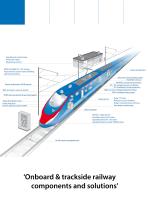
Signalling & control relays Protection relays Measuring sensors MSAV ultralight AC / DC energy measurement system (data handling and train functions) Door control units Electrical control (relay) panels Hall effect sensors MSAVDC energy measurement AC / DC voltage presence indicator ICP intelligent circuit protection High current / voltage protection relays iREP intelligent relay panels Power distribution (MCB) panels AWS automatic warning system TPWS train protection & warning system Relay blocks Alarm & indicator units Panel indicators Drivers advisory system (DAS) Relay 19” racks Miniature...
Open the catalog to page 4
Mors Smitt Railway technology Mors Smitt is entirely devoted to develop and manufacture electrical equipment, components and control solutions for railway and trackside applications. Mors Smitt has become leading in this demanding market. We supply the largest international rolling stock manufacturing enterprises as well as the main world rail operators. Mors Smitt has been manufacturing relays since 1902. We have a wide range of relays fit for all railway rolling stock applications. Our technology was developed in the 1960’s and has proven itself over time and is still the most reliable and...
Open the catalog to page 5
New solutions are co-designed with railway operators and contractors, creating safer railway networks
Open the catalog to page 6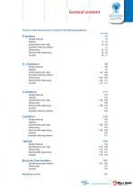
The Mors Smitt relay selection is divided in the following platforms: - Example ordering scheme 51 - Electrical life expectancy 54 - 55 - Example ordering scheme 103 - Electrical life expectancy 106 -113 - Electrical life expectancy 130 -132 - Example ordering scheme 134 - Electrical life expectancy 146 -149 Example ordering scheme 151 - Electrical life expectancy 176 -177 Electronic time modules 181 ^MITT" www.morssmitt.com
Open the catalog to page 7
Relay platforms Compact multi functional relays for all different kind of applications. Up to 4 change-over contacts these relays all have the same base of 40 x 40 mm. 8-pole configurations in different types also available. Heavy duty multi functional relays with very long mechanical contact life of 100 million cycles. Up to 4 change-over contacts these relays all have the same base of 45 x 45 mm. Different types available for many different applications. B-relays with higher continuous contact load and higher relay cover than A-relays. ThlMors Smitt Vj^r A Wabtec Company www.morssmitt.com VJMIT...
Open the catalog to page 8
Relay platforms Small relays up to 2 change-over contacts.These relays all have the same base of 20 x 30 mm and different models are available for different applications. Flat multi functional relays up to 9 change-over contacts and very long mechanical contact life of 100 million cycles. These relays all have the same base of 33 x 65 mm. Different models are available for different applications. Instantaneous Latching Flashing Monitoring Relays with different functionalities and options for many different applications. Ranging from 1 to 40 change-over contacts in different dimensions. Electronic...
Open the catalog to page 9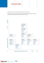
Selection table The details of each relay are described in the product pages in the next chapters. A first distinction can be made with 2 graphs. The first graph shows different relay platforms with respect to the number of contacts and the maximum continuous contact current. 401 / 407 relays Contacts: 40 N/O-N/C Max. cont. current: 8 A Safety critical Instantaneous Latching 303 / 310 relays Contacts: 19 N/O-N/C Max. cont. current: 8 A Safety critical Instantaneous Latching C-platform Contacts: 9 N/O-N/C Max. cont. current: 8 A Safety critical Instantaneous Latching Monitoring Flashing Maximum...
Open the catalog to page 10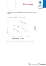
Selection table The second graph shows a comparison of different relay platforms with respect to their electrical life DC current breaking capacity (24 VDC resistive load) Comparison chart of life expectancy different relay platforms (for details see life expectancy curves of each relay) ^MITT" www.morssmitt.com
Open the catalog to page 11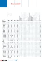
Special dust protection Push-to-test button Double make / double break Coil input Position indicator Gold bifurcated and silver contacts Manual reset control lever Gold contacts Integrated snap-lock Weld-no-transfer contacts Make before break contacts Double zener coil protection diode (transil) Mechanical keying relay to socket Polarisation diode Back EMF protection diode Current coil Selection table Delay on pull-in 2 Delay on drop-out 1
Open the catalog to page 12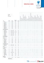
Push-to-test button - Position indicator Manual reset control lever Current coil Gold bifurcated and silver contacts Mechanical keying relay to socket Special dust protection Integrated snap-lock Make before break contacts Coil input Double zener coil protection diode (transil) Polarisation diode Double make / double break Gold contacts Weld-no-transfer contacts Back EMF protection diode Selection table Timer & instantaneous Delay on pull-in 2 Delay on drop-out 1
Open the catalog to page 13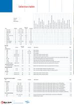
Back EMF protection diode Polarisation diode Double zener coil protection diode (transil) Make before break contacts Special dust protection Push-to-test button Coil input Specials Type Coil input Integrated snap-lock Weld-no-transfer contacts Current coil Double make / double break Position indicator Manual reset control lever Gold bifurcated and silver contacts Mechanical keying relay to socket Gold contacts Selection table Main features Ultra compact Ultra compact Ultra compact Safety-critical, weld-no-transfer contacts Safety-critical, weld-no-transfer contacts No auxiliary power supply necessary,...
Open the catalog to page 14
Compact multi functional relays for all different kind of applications. Up to 4 change-over contacts these relays all have the same base of 40 x 40 mm. 8 pole configurations in different types also available. ^MITT" www.morssmitt.com
Open the catalog to page 15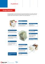
Design features The unique D-platform is specifically designed to solve demanding applications in the railway market: high DC breaking capacity and inductive load switching, offering long electrical life and low life cycle costs. The D-platform offers ultimate flexibility to be suitable for many railway applications. Joke + springs The joke + springs system is adjusted to calibrate the contact pressure of the normally closed contacts. Suitable for hazardous areas Corrosion resistant. Shock & vibration resistant. Integrated snap-lock. Switching capacity 1 mA...10 A (200 A overload). High DC breaking...
Open the catalog to page 16All Mors Smitt BV catalogs and technical brochures
 EazyPV+
1 Page
 Instaltest XB
1 Page
 KDN-R8
14 Pages
 TRD8
TRD812 Pages
 V88 Socket
9 Pages
 V33
V338 Pages
 Universal relays
12 Pages
 Products & services
16 Pages
 Signalling & rail infrastructure
20 Pages
 Activities brochure
12 Pages
 Relay Life Services brochure
8 Pages
 Mors Smitt Group
19 Pages
 Instruments 2
46 Pages
 Instruments 1
74 Pages
 Substation protection & control
12 Pages
 SPD - Surge Protection Devices
60 Pages
 brochure Railway activity
16 Pages
 Protection components
20 Pages
 Railway Technology
11 Pages
 Brochure Mors Smitt Goup
13 Pages
 Signalling relays BR930
11 Pages
 Brochure Door control units
11 Pages
 Brochure Protection components
11 Pages
 Miniature circuit breakers
17 Pages
 Engineered solutions
32 Pages
 Mors Smitt Heavy Duty Relays
100 Pages
 Mors Smitt Industrial Technology
24 Pages
 Mors Smitt Products & Services
12 Pages






- Switching relay
- Portable tester
- Circuit breaker
- Portable analyzer
- Digital tester
- Automatic tester
- Industrial tester
- Electromechanical relay
- Voltage testing system
- DC electromechanical relay
- Power quality analyzer
- Installation tester
- Insulation testing system
- Cabling tester
- Compact tester
- Current protection relay
- Digital protection relay