Catalog excerpts

* Patents Pending The TRUNKSAFE Fault-Tolerant Fieldbus System provides a cost-effective, yet highly reliable, strategy to maintain continuous communications between field devices and a Distributed Control System (DCS) in the event of any single point failure (such as an open- or short-circuit) on a FOUNDATION fieldbusٙ H1 or PROFIBUS PA segment. Delivers High-AvailabilityӔ Fieldbus Segments Designed for important and plant-critical fieldbus segments, TRUNKSAFE utilizes two trunk cables (or legsӔ) for physical layer redundancy to ensure no single point of failure will shut down the network.Under normal operation, the fieldbus segment isterminated at each end of the segment at the TRUNKSAFE Redundant Power Conditioners. TRUNKSAFE maintains fieldbus communications throughout the entire segment until a fault (open- or short-circuit) is detected. Upon fault detection, the TRUNKSAFE Device Coupler initiates its automatic segment termination so that the healthy leg is properly terminated. This automatic fault detection and termination allows uninterrupted fieldbus commu- nications throughout the segment (see Figure 1). The host is informed about the fault via a contact closure output.TRUNKSAFE is fully compliant withFOUNDATION fieldbus FF831-1 (the technical specification for fieldbus power supplies) and FF846-1 (the technical specification for device couplers). > TRUNKSAFE Fieldbus Device Couplers and PowerConditioners install on a DIN-style rail. Device couplers canbe ordered in rugged field-mount enclosures with cable glands. Compatible with FOUNDATION Fieldbus H1 andPROFIBUS PA networks. Complete redundant fieldbus physical layer. Delivers solutions to common fieldbuscommunication faults. Completely compliantwith fieldbus physical layer standard IEC 61158-2; no modification is required to fieldbus devices or to DCS-level software.Օ TRUNKSAFE is comprised of two redundant fieldbus DC power conditioners and a specially- engineered device coupler that, in combination, provide a secure, and redundant, fieldbus physical layer. Advanced fieldbus physical layer diagnostics. TRUNKSAFE Diagnostic Modules offer simple hardware-based alarm LEDs for DC power status and segment noise. An optional TRUNKSAFE Diagnostics Module monitors device transmission errors and reports via MODBUS RTU for easy integration into asset management systems (see Page 6). TRUNKSAFEautomatically maintains continuous segment communications even in the event of a cable break (open- or short-circuit) or failures to a TRUNKSAFE Power Conditioner.Օ Fault-Tolerant Protection AgainstAll Physical Layer Faults One difficulty still remains with fieldbus technology: all segment communications and power integrity are vulnerable to a single broken twisted wire cable. Until now, the only ways to protect plant- critical segments were expensive duplication of an entire segments hardware, complex software voting schemes and restricting the number of devices per segment. With TRUNKSAFE, critical process loops can use fieldbus technology without worrying about cable failures. This allows full access to advanced diagnostics and uninterrupted measurement and control communications that can be realized using fieldbus technology. > All product names are registered trademarks of their respective companies. ҩ 2007 Moore Industries-International, Inc. 920156A Page 1 size="-1">
Open the catalog to page 1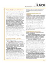
Typical Application In a typical TRUNKSAFEapplication, redundant H1 cards are wired out to TRUNKSAFEגs Redundant Power Conditioners (one for each H1 card). Trunk cables are then run from each power conditioner to the TRUNKSAFE Device Coupler. Both power conditioners provide power to the device coupler through different trunk cables. Fieldbus terminators are provided at each power conditioner in normal operation.Completely compliant with IEC 61158-2, thesystem will support a total cable length including the redundant leg and spurs of up to 1,900 meters (6,233 feet. > The TRUNKSAFE...
Open the catalog to page 3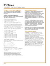
The TRUNKSAFE Redundant Fieldbus Systemdelivers comprehensive diagnostic capabilities at every level. A TRUNKSAFE Fieldbus Segment Splitter installs between the H1/PA interface card(s) and the TRUNKSAFE segment, and routes the fieldbus signal to both trunks of the TRUNKSAFE network. The Fieldbus Segment Splitter has no effect on the operation or performance of the H1/PA cards, and is typically mounted in close proximity to the H1/PA card or module.TRUNKSAFE Fieldbus Segment Splitters are avail-able to accommodate the architectures of the major DCS manufacturers including ABB, Emerson...
Open the catalog to page 6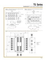
Figure 2. TPS201/202 Advanced Power Conditioner with DIN-Rail Mounting Installation Dimensions. Figure 3. TS200 Device Coupler DIN-Rail Mounting InstallationDimensions (Base Unit). > 82mm (3.23 in) 127mm(5.00 in)6-Spur (Shown)204mm(8.05 in)12-Spur 51mm(1.99 in) TOP VIEW SIDE VIEW 122mm(4.80 in) 216mm(8.50 in) 114mm(4.49 in)TOP VIEW SIDE VIEW(Shown with SPM Surge Protection Modules Installed on Each Spur) Figure 4. Standard Aluminum Enclosure Installation Dimensions for 6-Spur (TS256) and 12-Spur (TS25W) Models. > 322mm (12.68 in) 175mm (6.89 in) 156mm (6.14 in) 274mm (10.79 in) 293mm (11.54...
Open the catalog to page 7
3 5mm (1.50 in)MIN CLEARANCE FOR LID REMOVAL 3 19mm (12.56 in) > :CLEAN ONLY WITH DAMP CLOTH Model No :T A S S S eri a l No : CA, U s URE S a g No : l North Hill a TRUNKGUARD tion a TIC ENCLO S erie s 200 Device Co u pler -Intern S s trie us FOR PLA Moore Ind 260mm (10.24 in) > P a dlock fixing S TUD M10DIA. 10mm (0. 3 94 in) 1 83 mm (7.20 in) 224mm ( 8 . 8 2 in) 24 8 mm (9.76 in) GROUND REMOVABLE GLAND PLATE1 3 5mm x 175mm (5. 3 1 in x 6. 8 9 in)PRE-DRILLED M20 ENTRIE S 2x PLATE S > TRUNKSAFE Series 200 Device Coupler FOR PLASTIC ENCLOSURES:CLEAN ONLY WITH DAMP CLOTH Moore...
Open the catalog to page 8All Moore Industries catalogs and technical brochures
-
SB
2 Pages
-
LH
2 Pages
-
TMZ
8 Pages
-
CPT (Current/Voltage Input)
8 Pages
-
CCS - Cable Concentrator System
12 Pages
-
HIM HART® Interface Module
8 Pages


