- Catalogs
- Moore Industries
- Signal Transmitters, Isolators and Converters
Signal Transmitters, Isolators and Converters
Signal Transmitters, Isolators and Converters
Signal isolators, converters, and interfaces are crucial in process instrumentation, addressing issues like ground loops and signal conversion. They enhance process signals by sharing, splitting, boosting, protecting, stepping down, linearizing, and digitizing them.
Signal isolation became essential with electronic transmitters in the 1960s to prevent inaccuracies from ground loops. Isolators break the galvanic path between circuits, eliminating unwanted current flow.
Optical Isolation uses light for signal transfer, offering excellent noise rejection. Transformer Isolation uses electromagnetic coupling, effective for AC signals but requires conversion for DC signals.
Two-way isolation involves input-to-output isolation, suitable for 2-wire transmitters. Three-way isolation includes power-to-input and power-to-output isolation, necessary for 4-wire isolators.
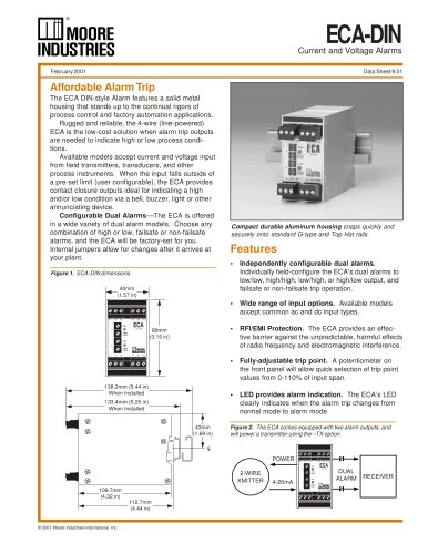
Converters adapt legacy signals to modern standards, such as converting 10-50mA to 4-20mA. Options include fixed-range, configurable, and PC-configurable converters.
AC signal converters step down dangerous signals for safe monitoring. Digital conversion, like HART to MODBUS RTU, integrates HART data into non-native systems.
Isolators/converters can be 4-wire (line-powered) or 2-wire (loop-powered), with 4-wire units offering more output options.
The isolator consumes 5.5V from the loop, appearing as a 275-ohm load. The total burden on the transmitter can reach 525 ohms, manageable for 4-wire but challenging for loop-powered transmitters.
Signal isolators allow maintenance on one system without affecting others. Signal splitters divide one input into multiple outputs, useful in applications like custody transfer.
Passive inputs remain unaffected if power is lost. Bucking power supplies solve issues with DCS input cards by accommodating powered inputs from both sides.
Powering a 2-wire transmitter from a 4-wire isolator is cost-effective. Compliance voltage drives the output current, related to drive capacity.
Isolators add drive capability to loops. They can pass or block HART signals, allowing access to diagnostics or preventing unauthorized changes.
These instruments save space by combining channels. Premium isolators ensure alarms trip as required.
Microprocessor-based isolators offer custom linearization, useful for applications like tank level to volume conversion.
The document provides a guide on signal isolators, converters, and interfaces, focusing on specifications, applications, and environmental considerations.
Emphasizes solid aluminum cases to block RFI/EMI and the use of filters to mitigate noise. Output damping manages noisy signals.
Discusses installation in hazardous areas and the impact of ambient temperature on performance.
Outlines design features to prevent interference and solutions for noise from Variable Frequency Drives.
Provides a checklist for selecting the appropriate signal isolator, converter, or interface.
Concludes with contact details for regional offices and an invitation to use the E-HELP EXPRESS service.
Catalog excerpts

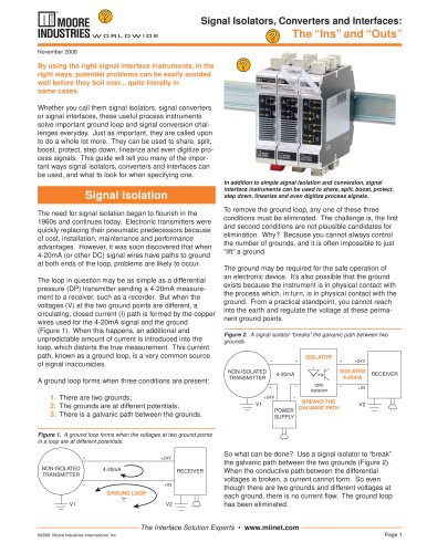
November 2008 By using the right signal interface instruments, in the right ways, potential problems can be easily avoided well before they boil over... quite literally in some cases. Whether you call them signal isolators, signal converters or signal interfaces, these useful process instruments solve important ground loop and signal conversion chal- lenges everyday. Just as important, they are called upon to do a whole lot more. They can be used to share, split, boost, protect, step down, linearize and even digitize pro- cess signals. This guide will tell you many of the impor- tant ways signal isolators, converters and interfaces can be used, and what to look for when specifying one. > In addition to simple signal isolation and conversion, signal interface instruments can be used to share, split, boost, protect, step down, linearize and even digitize process signals. The need for signal isolation began to fl ourish in the 1960s and continues today. Electronic transmitters were quickly replacing their pneumatic predecessors because of cost, installation, maintenance and performance advantages. However, it was soon discovered that when 4-20mA (or other DC) signal wires have paths to ground at both ends of the loop, problems are likely to occur. The loop in question may be as simple as a differential pressure (DP) transmitter sending a 4-20mA measure- ment to a receiver, such as a recorder. But when the voltages (V) at the two ground points are different, a circulating, closed current (I) path is formed by the copper wires used for the 4-20mA signal and the ground (Figure 1). When this happens, an additional and unpredictable amount of current is introduced into the loop, which distorts the true measurement. This current path, known as a ground loop, is a very common source of signal inaccuracies.A ground loop forms when three conditions are present: To remove the ground loop, any one of these three conditions must be eliminated. The challenge is, the fi rst and second conditions are not plausible candidates for elimination. Why? Because you cannot always control the number of grounds, and it is often impossible to just liftӔ a ground. The ground may be required for the safe operation of an electronic device. Its also possible that the ground exists because the instrument is in physical contact with the process which, in turn, is in physical contact with the ground. From a practical standpoint, you cannot reach into the earth and regulate the voltage at these perma- nent ground points. > Figure 2. A signal isolator ғbreaks the galvanic path between two grounds. ISOLATOR +24V+Ԗ++֖ NON-ISOLATED TRANSMITTER4-20mA ISOLATED4-20mABREAKS THEGALVANIC PATH RECEIVER RECEIVER optoisolation +IN 1. There are two grounds; > +24V 2. The grounds are at different potentials; > V1 V2 3. There is a galvanic path between the grounds. > POWER SUPPLY Figure 1. A ground loop forms when the voltages at two ground points in a loop are at different potentials. +24V+֖ So what can be done? Use a signal isolator to breakӔ the galvanic path between the two grounds (Figure 2). When the conductive path between the differential voltages is broken, a current cannot form. So even though there are two grounds and different voltages at each ground, there is no current fl ow. The ground loop has been eliminated. > NON-ISOLATED TRANSMITTER 4-20mAV2 RECEIVER RECEIVER +IN GROUND LOOP IӔ V1 The Interface Solution Experts www.miinet.com > թ2008 Moore Industries-International, Inc. Page 1 size="-1">
Open the catalog to page 1
Transformer Isolation Transformer isolation (Figure 4), often referred to as electromagnetic isolation, uses a transformer to electromagnetically couple the de- sired signal across an air gap or non-conductive isolation gap. The electromagnetic fi eld intensity is proportional to the input signal applied to the transformer. Transformers are very effi cient and fast at transferring AC (alternating current) signals. Since many process control signals are DC, they must be electrically דchopped into an AC signal so they can pass across the transformer. Once passed, they have to be rectifi ed and...
Open the catalog to page 2
Normally when you think of isolators, you think of solving a problem at the instrument control level layer, typically dealing with DC signals. However, very common applica- tions use a signal converter to monitor, trend or alarm on AC signals. With preventative maintenance budgets shrinking, companies are closely monitoring expensive and critical equipment purchases. Pumps, motors and fans are quick to fall into this category. Since much of this equipment is powered with AC volt-age, and high levels of current, a current transformer (CT) is installed. The role of a CT is two-fold. First, a CT...
Open the catalog to page 3
A new emerging method of converting signals ignores all the previous rules laid down by analog isolators and con- verters. This new digital signal conversionӔ is becoming especially popular in locations where power is sparse and wires are few. A common application deals with digitally converting or mappingӔ HART > A signal isolator/converter can be 4-wire (line/mains- powered) or 2-wire (loop-powered). Selecting the correct type of isolator and power confi guration depends on the application. 4-Wire (Line/Mains-Powered) Signal Isolators A4-wire isolator/converter (Figure 8) is used when the instrument...
Open the catalog to page 4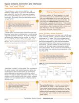
Moore Industries Instrument Recommendations:MIX 2-Wire Multi-Channel Signal Isolator/Converter ECT 2-Wire (Output Loop-Powered) Signal Isolator/Converter SIY 2-Wire PC-Programmable Signal Isolator/Converter SDY 2-Wire PC-Programmable Signal Isolator/Converter with Display > Figure 12. A signal splitter takes one signal input and provides two or more identical outputs proportional to the input. > Transmitter Excitation (TX): +A +OUT Isolator Powers a 2-Wire Transmitter ISOLATED 4-20mA RECEIVER1 24V ISOLATORSPLITTER +ז NON-ISOLATED2-WIRETRANSMITTER +TX+IN A OUT֖ 4-20mA B +OUTB OUT Moore Industries...
Open the catalog to page 6
Figure 15. A HART isolator allows the HART digital signal to pass through the isolator. > HART DIGITAL SIGNAL HART DIGITAL SIGNAL +24V+IN+24V+IN+Ԗ + ISOLATED2-WIREHART TRANSMITTER ISOLATED 4-20mA Loop ISOLATED4-20mA Loop DCS + ֖ HARTISOLATOR Moore Industries Instrument Recommendations:MIX 2-Wire Multi-Channel Signal Isolator/Converter ECT 2-Wire (Output Loop-Powered) Signal Isolator/Converter SIY 2-Wire PC-Programmable Signal Isolator/Converter SDY 2-Wire PC-Programmable Signal Isolator/Converter with Display Moore Industries Instrument Recommendations: HIX Figure 14. A signal isolator adds more...
Open the catalog to page 7All Moore Industries catalogs and technical brochures
 SB
SB2 Pages
 LH
LH2 Pages
 TMZ
TMZ8 Pages
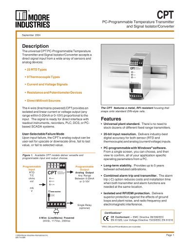
 CPT (Current/Voltage Input)
8 Pages
 CCS - Cable Concentrator System
12 Pages
 HIM HART® Interface Module
8 Pages


- SARRALLE temperature sensor
- Plastic housing
- SARRALLE metal enclosure
- Circuit breaker
- Thermocouple temperature transducer
- Indoor enclosure
- Protection housing
- Electronic housing
- Electronic display panel
- Outdoor housing
- Programmable display system
- Power distribution box
- Temperature transmitter
- Instrumentation enclosure
- Pressure transducer
- Enclosure with door
- IP66 box
- Analog pressure transducer
- Insertion temperature sensor