
- Catalogs
- Moore Industries
- Limit Alarm Trips and Switches

Limit Alarm Trips and Switches

Limit Alarm Trips and Switches
The document explores the functionality of limit alarm trips in industrial processes, which monitor process signals and activate relay outputs when signals exceed preset limits, ensuring safe operations.
Hard alarms are independent, hard-wired systems providing relay outputs, offering redundancy and critical safeguarding, unlike software-based soft alarms in DCS or PLC systems, which are prone to common-mode failures.
Limit alarm trips perform functions from simple annunciation to complete process shutdown by activating relay outputs when monitored variables exceed user-set trip points, ensuring continuous supervision.
These alarms trigger warnings or initiate emergency shutdowns when a monitored variable exceeds preset high or low trip points, with multiple relay outputs for different protection levels.
Alarm trips can have multiple relay outputs for configurations like high/high, low/low, and high/low alarms, providing various levels of warnings and emergency responses.
Rate-of-change alarms detect changes over time, input fault alarms alert to sensor interruptions, and self-diagnostic alarms monitor their own status, with average and differential alarms responding to input signal variations.
Different relay configurations, including SPST, SPDT, and DPDT, are used to control current flow and perform multiple functions simultaneously.
Failsafe configurations ensure relays de-energize in alarm conditions for safety during power failures, while non-failsafe configurations do not provide warnings during power failures.
The document discusses integrating Normally-Open/Normally-Closed and Failsafe/Non-Failsafe relay actions to ensure alarms are detected even during power failures.
- Non-Failsafe Relays: De-energized in a normal state and energized in an alarm state, switching contacts from NC to NO when a trip point is exceeded.
- Failsafe Relays: Energized in a normal state and de-energized in an alarm state, switching contacts from NO to NC when a trip point is exceeded.
Deadband prevents relay chatter by setting it away from the trip point, and time delays prevent false alarms by ensuring the trip point is exceeded for a specific duration before triggering an alarm.
Latching alarms require manual reset by an operator, while non-latching alarms reset automatically.
Relays have contact ratings from one to ten amps, and exceeding these ratings can cause damage. Load behavior, such as inrush currents, must be considered to prevent relay damage.
Some alarm trips provide 24Vdc power to a 2-wire transmitter, eliminating the need for an additional power supply.
A 2-out-of-3 voting scheme can be used in critical processes to prevent false alarms, triggering an alarm only if two out of three sensors indicate a fault.
The document emphasizes the role of hard alarm trips in safety-related applications, particularly in compliance with IEC 61508 standards, with FMEDA reports evaluating device reliability in safety systems.
Limit alarm trips are crucial for maintaining safety and operational integrity in industrial processes, with designs increasingly meeting safety standards like IEC 61508 for enhanced safety and reliability.
Catalog excerpts

June 2006 Something happensa signal peaks or fallsחandyou need to know. A limit alarm trip can trigger the response needed to maintain normal, and safe, operations. A limit alarm trip monitors a process signal (such as one representing temperature, pressure, level or flow) and compares it against a preset limit. If the process signal moves to an undesirable high or low condition, the alarm activates a relay output to warn of trouble, provide on/off control or institute an emergency shutdown.While limit alarm trips are best known as a sure way toactivate a warning light, siren or bell when a process problem occurs, they are also called upon to do much more. In fact, todays highly flexible and versatile alarm trips can be found working in a wide range of applications, under an impressive list of pseudonyms. Here are just some: > Independent ғhard alarm trips can be usedto warn of trouble, provide on/off control ortrigger an emergency shutdown. Because they are hard-wired into the process and provide relay outputs, independent limit alarm trips are often referred to as ԓhard alarms. This term differentiates a ԓhard alarm trip from the software- implemented alarm (a ԓsoft alarm) which is found within a Distributed Control System (DCS) or a programmable logic controller (PLC). Hard-Wired AlarmTrip AlarmOn/Off Controller Limit SwitchTrip Amplifier or Trip AmpRange Alarm Safety ShutdownLevel ControllerSafety Interlock Redundant ShutdownTemperature, Voltage or Current AlarmHigh/Low Controller High Integrity SwitchEmergency ShutdownCurrent or Temperature Switch Sensor Failure MonitorComparatorTemperature Averaging Alarm Supervisory AlarmDifferential AlarmRate-of-Change Alarm Shutdown AlarmFailsafe AlarmFault Monitor Failsafe ShutdownWindow Alarm > Most every plant performs alarm functions using ԓsoft alarms within their DCS or PLC. As such, some might argue that ԓhard alarms are not necessary. However, ԓhard alarm trips complement DCS and PLC systems > Figure 1. Limit alarm trips monitor a process signal and send oneor more relay outputs when a monitored signal exceeds preset highand/or low limits (dual high/low alarm configuration shown). DUAL HIGH/LOW ALARM TRIP Change in Input Signal Change over Time The Interface Solution Experts ԕ www.miinet.com > 2006 Moore Industries-International, Inc. Page 1 size="-1">
Open the catalog to page 1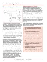
+PSՖPS24V+ININ+IN DCSORPLC 2-WIRE TRANSMITTER > 4-20mA Loop 250 ohmResistor 1-5V EMERGENCYSHUTDOWNSYSTEM,(ESD) "HARD" LIMITALARMTRIP > EmergencyShutdown
Open the catalog to page 2
High and Low Limit Alarms > Figure 4. Multiple relay outputs allow one limit alarm trip to monitorcombinations of high, low and input fault conditions A high or low limit alarm is triggered when the value of thevariable being measured exceeds a preset high or low alarm trip point (Figure 3). This type of alarm trip monitors temperature, pressure, level, flow, position or status variables, and is typically used to warn of unwanted process conditions or to provide emergency shutdown. . > Annunciator Limit AlarmTrip Figure 3. Dual high/low limit alarm trip with deadband to reduce relaychatter ....
Open the catalog to page 3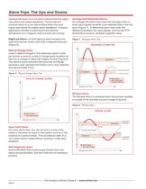
High/Low Alarm A dual high/low alarm accepts oneinput and has two relays, each with a separate trip point (Figure 3). contacts will return to a non-alarm status when the signalrises above the lowest deadband. The low alarmגs contacts return to a non-alarm status when the input signal rises above the higher alarm deadband. A typical application includes monitoring the low extreme temperature of a cryogenic tank to avoid over-cooling. Average and Differential Alarms An average limit alarm trips when the average of two orthree input signals exceeds a pre-selected high or low trip point (Figure 7)....
Open the catalog to page 4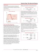
On/Off Control > Figure 10. Single-Pole/Single-Throw (SPST) Relay shown with anormally-open (NO) contact in the de-energized (shelf) state A limit alarm trip can also be used as a simple on/off controller such as those required in level applications (pump/valve control) when filling or emptying a container or tank (Figure 9). . > SINGLE-POLE/SINGLE-THROW CNO > Figure 9. On/Off Control . FORM A > ON/OFF CONTROLLER Single-Pole/Double-Throw (SPDT) A SPDT contacthas one pole and sends the electrical path in one of two directions (Figure 11). By providing both the NO and NC contacts, this type of...
Open the catalog to page 5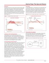
Deadband Time Delay The alarm trip fires its relay at the trip point and the relayresets when the process variable reaches the deadband point. Without deadband, if the process variable was hovering and cycling above or below the trip point, the relay would be chattering on and off, leading to premature failure. By setting the deadband just one or two percent away from the trip point, you can avoid excessive relay wear (Figure 17). In many applications, a momentary over-range signal may not warrant an alarm trip. Some alarm trips can be set with an alarm response time delay that stops the alarm...
Open the catalog to page 7All Moore Industries catalogs and technical brochures
 SB
SB2 Pages
 LH
LH2 Pages
 TMZ
TMZ8 Pages
 CPT (Current/Voltage Input)
8 Pages
 CCS - Cable Concentrator System
12 Pages
 HIM HART® Interface Module
8 Pages














- Display module
- Temperature probe
- Plastic housing
- Metal box
- Circuit breaker
- Thermocouple temperature transducer
- Indoor enclosure
- Electronic display panel
- Protection housing
- Electronic housing
- Programmable display system
- Outdoor housing
- Power distribution box
- Instrumentation enclosure
- Temperature transmitter
- Pressure transducer
- Enclosure with door
- Analog pressure transducer
- Insertion temperature sensor
- IP66 housing