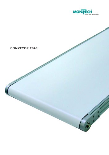
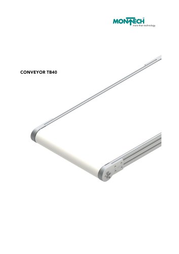
Conveyor TB40
1 /24Pages
Conveyor TB40
1 /24Pages
Catalog excerpts

more than techn
Open the catalog to page 1
Conveyors TB40 are used to carry parts to or from the various manufacturing stations, or combined to form comple- te transport systems. The modular construction of the system permits simple adaptation to specific customer The conveyor is driven by a 24 V motor. This permits trans- portation of up to 80 kg in the conveying mode. Conveyor products are complemented by our full range of accessories. This includes various belt types for different applications, lateral guides and stands. The warranty is 36 months from date of delivery. Modifications may be made without notice.
Open the catalog to page 3
With the drive integrated into the drive roller, the conveyor belt is very compact in design. The following chassis widths are available: 300, 400, 500, 600, 700 and 800 mm. The possible band length is between 1 and 6 m. The diameter of the deflection rollers is 60 mm (the drive roller is 73 mm) and allows the use of cleated belts. The compact construction delivers huge benefits especially for climbing conveyors provided with cleat spacing with ribs. Accessories can be included in the future easily, quickly and without mechanical processing.
Open the catalog to page 4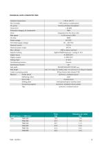
TECHNICAL DATA CONVEYOR TB40 Ambient temperature normal workshop atmosphere Noise level Protection category of components integrated into the drive roller Belt speed Rated voltage Permitted supply voltage Nominal current Nominal power output Setpoint setting digital (PWM-frequency) / analog 0 –10 V Digital inputs Digital outputs Analog input Anti-blocking function Overload protection Belt width Belt length min. 1 m / max. 6 m (belts under 1 m and over 6 m long on request) Load in conveying mode Material Profile lateral aluminum, anodized natural Deflecting rollers Drive roller stainless steel...
Open the catalog to page 5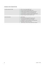
TECHNICAL DATA CONVEYOR TB40 Functions electronics TB40 Start / stop through digital input Direction selection through digital input Stepless speed modification through analog input 3 stored speeds to choose through digital input Overtemperature message through the digital output General description Ready message through the digital output BLDC Motor Drive with fully integrated 4Q operating and control electronics with sinus commutation Possibility for smooth acceleration and deceleration Operating in speed control mode (positioning or torque mode available upon request)
Open the catalog to page 6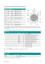
DESCRIPTION OF MOTOR CONNECTIONS CONVEYOR TB40 15-pin connector (M16) Pin 1 The speed setpoint can be preset through the analog input (potentiometer) and/or the predefined constant speeds are used. With the corresponding bit pattern, the direction, the rotational speed and the driving state (start / stop) can be selected. 1) The analog input is connected to a potentiometer R = 10 kΩ. rotation direc. speed setpoint through analog input AIN 1 variable speed 1 (default: 10 m/min) variable speed 2 (default: 20 m/min) variable speed 3 (default: 30 m/min) speed setpoint through analog input AIN 1 variable...
Open the catalog to page 7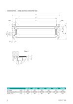
CONSTRUCTION / CROSS-SECTION CONVEYOR TB40 A B 0.25 B conveyor width ± 0.5 mm [mm] X belt width
Open the catalog to page 8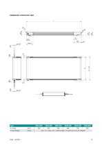
min. 1m / max. 6 m – belts under 1 m and over 6 m on request
Open the catalog to page 9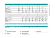
Manufacturer’s designation Edge radius Operating temp., cont. Operating temp., briefly Field of use Method of transport horizontal inclined Surface of conveying side Cleats Color of conveying side dark green Conveying mode coefficient of friction µG at 50% relative humidity Deflection roller Buffering mode coefficient of friction µG at 50% relative humidity Deflection roller Legend Required force for 1% elongation k1% kperm. Maximum permissible force L Food Ch Chemistry Ph Pharmaceuticals Mounting systems, genera Electronics industry (electrically conductive) Effect of oil and grease For high...
Open the catalog to page 10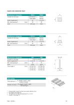
CLEATS FOR CONVEYOR TB 401) Manufacturer’s designation Manufacturer’s designation Suitable for belt type Manufacturer’s designation Suitable for belt type Field of application Color Cleat height h Min. cleat spacing A Color Suitable for belt type Cleat spacing 4) Cleat spacing A = 2 × length L [mm] + 66.5 number of cleats 4) Number of cleats = 2 × length L [mm] + 66.5 cleat spacing A Cleated belts require at least two weeks delivery time For legend, see page 10 The tolerance of the cleat spacing A is ± 2 mm Length L see page 14
Open the catalog to page 11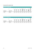
LOADING LIMITS CONVEYOR TB40 Belt speed Belt width End- drive in conveying mode Belt speed Belt width End drive in buffering mode
Open the catalog to page 12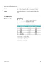
BELT FABRICATION CONVEYOR TB40 Version 1 You order the belt yourself from the manufacturer in the table below. You can determine the belt length using the file Gurtlange TB40.xls. Version 2 Montech procures the belt for you according to the list of belt codes LIST OF BELT CODES Connection code (see code below) Belt length (always 5-digit) Belt length (always 4-digit) Belt number (see code below) Connection code 1 = endless flexproof Connection code 2 = endless thermofix Connection code 3 = open beveled Connection code 4 = cut square Connection code 1 is prefarable!
Open the catalog to page 13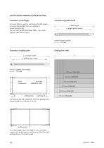
CALCULATION FORMULAS CONVEYOR TB40 Calculation of belt length Calculation of profile lateral L belt length LS length profile lateral Lateral formula profile: LS = L – 173 mm Calculation of gliding plate Gliding plate width LG L conveyor length LG gliding plate length Formula gliding plate length: LG = L – 159 mm drive component end with deflection roller gliding plate On the end side with deflection roller the gliding plate always needs an overhang of 14 mm. section point At a total length more than 3000 mm for assembly reasons the section point must have no offset from the gliding plate to the...
Open the catalog to page 14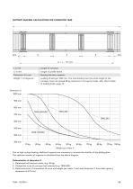
SUPPORT SPACING CALCULATION FOR CONVEYOR TB40 L Length of profile lateral Spacing between supports Loading of belt per 1000 mm. The total loading over the entire length of the conveyor must not exceed 80 kg maximum in conveying mode, refer also to table of loading limits, page 12. Weight per meter Y Due to high surface loading, additional supports are necessary to increase the stability of the gliding plate. The optimum number of supports is calculated from the above diagram. Determination of dimension X 1. Determine belt load per meter (e.g. 50 kg). 2. Choose the curve of conveyor belt selected...
Open the catalog to page 15All MONTECH catalogs and technical brochures
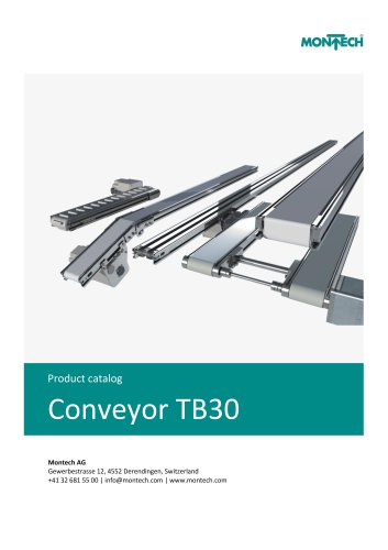 CONVEYOR TB30_2022
62 Pages
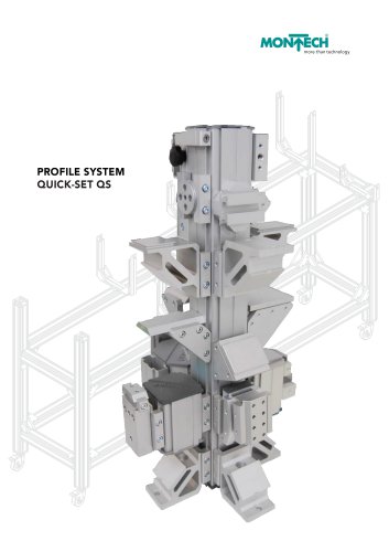 PROFILE SYSTEM QUICK-SET QS
68 Pages
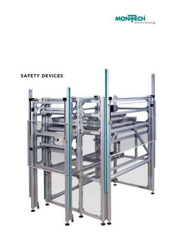 SAFETY DEVICES
30 Pages
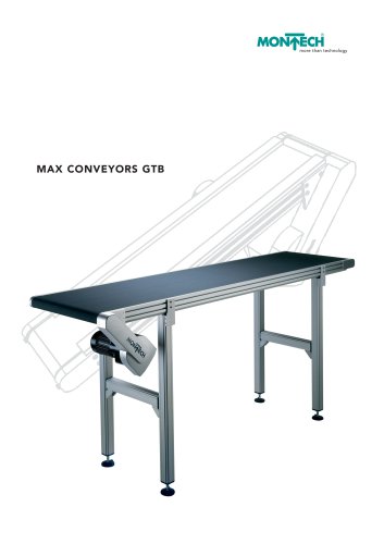 MAX CONVEYORS GTB
28 Pages
 TB40 Conveyor
45 Pages
 RB40 Roller Conveyor
18 Pages
 TILTING MODULE SOLTB-W�
2 Pages
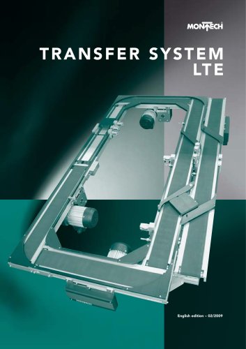
 Transfer System LTE
52 Pages
 Multitrack Conveyor MTB
2 Pages
 Vacuum Conveyor SOLTB-V
2 Pages
 Centering Conveyor SOLTB-Z
2 Pages
 Short Conveyor SOLTB-K
2 Pages
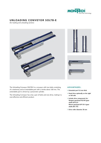 Unloading Conveyor SOLTB-E
2 Pages
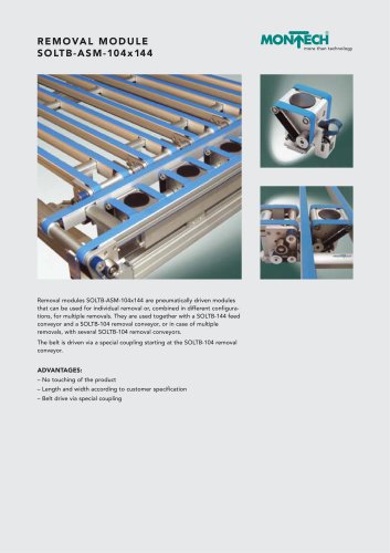
 Removal Module SOLTB-ASM
8 Pages
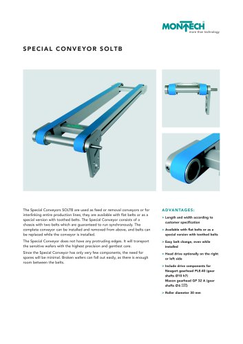 Special Conveyor SOLTB
2 Pages
 Transport System LT40
40 Pages
 Max Conveyors GTB
50 Pages
 Conveyor for cleanrooms TBR
3 Pages
 Conveyors TB
54 Pages
 Basic Conveyors BTB
35 Pages
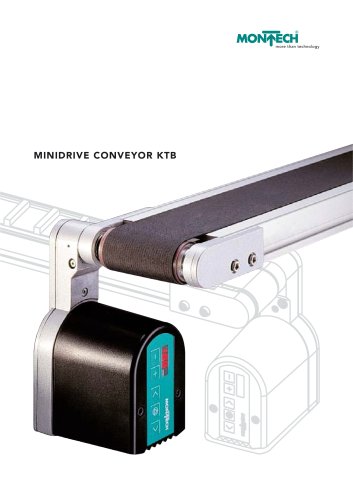 Minidrive Conveyors KTB
36 Pages

Archived catalogs
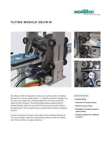 Tilting Module SOLTB-W
2 Pages
 Conveyors Manual
154 Pages
 Montrac Manual
100 Pages
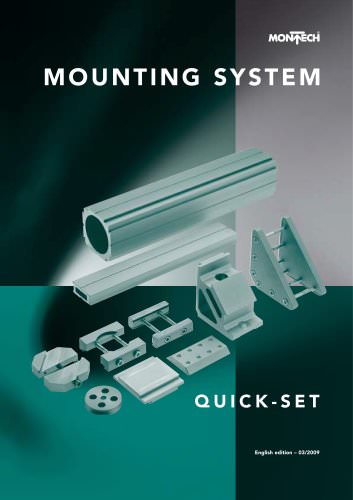 Mounting System – Quick-Set
116 Pages
 Conveyors – Transfer System LTE
52 Pages
 The World of Conveyors
16 Pages
 Automation – Linear units LEP
32 Pages
 Automation – Grippers
63 Pages
 Automation – Rotary drives DAP
34 Pages
 Automation - Lifting Devices HE
11 Pages
 Automation – Accessories
6 Pages


- Transport rail conveyor
- Belt conveyor
- Horizontal conveyor
- Metal profile
- Plastic cap
- Cylindrical cap
- Roller conveyor
- Electric drive conveyor
- Work conveyor
- Stainless steel conveyor
- Modular conveyor
- Aluminum profile
- Bulk material conveyor
- Rectangular profile
- Pallet conveyor
- Transfer conveyor
- Cardboard box conveyor
- Vertical conveyor