
- Catalogs
- MOLDINO Tool Engineering Europe GmbH
- Turning Inserts


Turning Inserts

Turning Inserts
Overview
This document is a detailed technical guide and catalog for turning inserts used in machining operations. It covers insert shapes, chip breakers, material grades, coatings, cutting conditions, and availability, providing comprehensive data to optimize tool selection and machining performance.
1. Insert Shapes and Types
Turning inserts are categorized by shape and application, including diamond (80°, 55°, 35°), square (90°), triangle (60°), hexagonal (80°), and round (360°) inserts. Separate tables specify shapes optimized for different materials such as steels, stainless steels, and cast irons. Insert geometry, including corner angles and nose radius, directly influences cutting performance.
2. Chip Breakers
Chip breakers are classified by cutting application: finishing, semi-finishing, medium cutting, and roughing. They differ in cross-sectional shape and chip removal region, with specific types recommended based on material (steel, stainless steel, cast iron) and cutting conditions (depth of cut, feed rate). Proper breaker selection enhances chip control, machining stability, and surface finish.
3. Material Grades for Inserts
HITACHI carbide grades are detailed, categorized by machining type (finishing, general, roughing) and workpiece material (carbon steels, alloy steels, stainless steels, cast irons, hardened materials, non-ferrous metals, super alloys, titanium). Each grade balances mechanical and physical properties such as hardness and toughness to optimize performance.
4. Coating Materials and Features
Coatings include PVD (e.g., IP050S, IP100S) and CVD types (e.g., HG3305), with thicknesses ranging from 5μ to 15μ. Key coating materials are TiN, Al2O3, TiC, TiCN, and Zr-added films. Coatings improve wear resistance, toughness, and chipping resistance, tailored to specific applications like stainless steel, cast iron, and interrupted cutting.
5. Recommended Cutting Conditions
Tables provide standard cutting parameters—depth of cut, feed rate, and cutting speed—matched to insert grades, chip breakers, and workpiece materials. For example, finishing operations with CZ25 inserts recommend speeds of 150–300 m/min and feed rates of 0.1–0.2 mm/rev. These parameters are critical for maximizing tool life and machining quality.
6. Insert Designations and Geometry
The document explains insert designation codes covering shape symbols, clearance angles, chip breaker presence, hole types, thickness, and tolerances (nose height, inscribed circle diameter). Cutting edge conditions (sharp, chamfered, rounded) and feed direction symbols are also described, aiding precise insert identification and application.
7. Cross-Reference of Insert Grades
Cross-references among manufacturers (Hitachi Tool, Tungaloy, Mitsubishi Material, Sumitomo Electric, Sandvik, Kyocera) are provided, highlighting equivalent grades with enhanced wear and breakage resistance. This facilitates sourcing flexibility and informed selection across brands.
8. Catalog Specifications and Availability
The catalog lists insert item codes, dimensions (inscribed circle diameter, thickness, nose radius, hole diameter), material types (carbide, cermet), and coating status (PVD coated or non-coated). Availability is indicated by symbols: ● (stocked), − (not manufactured), △ (made-to-order after stock depletion or after January 2011), and no mark (manufactured on request). This supports procurement planning and inventory management.
Critical Information and Best Practices
- Insert corner angles range from 35° to 360°, affecting cutting geometry and application.
- Chip breakers are matched to cutting depths: finishing (<1 mm), semi-finishing (0.5–1.5 mm), medium (1.5–4 mm), roughing (>4 mm).
- Feed rates and depths of cut are tabulated per breaker and material combination for optimal performance.
- Material grades and coatings are selected to balance wear resistance, toughness, and cutting efficiency.
- Coating thickness and composition directly influence durability and cutting performance.
- Substrate hardness and toughness must align with cutting conditions (continuous vs. interrupted).
- Physical properties such as hardness, strength, thermal conductivity, and expansion guide insert selection.
- Insert geometry, including clearance angles and chip breaker design, impacts machining efficiency and chip control.
- Cross-manufacturer grade equivalences enable flexible sourcing and application.
- Stock status symbols are essential for procurement planning to avoid delays.
Recommendations
- Select inserts based on machining requirements, material compatibility, and desired surface finish.
- Use coated inserts (PVD or CVD) for enhanced wear resistance in demanding operations.
- Refer to chip breaker codes and cutting condition tables to optimize chip control and tool life.
- Verify stock availability before ordering to ensure timely delivery.
- Plan for transition items marked with △ as they may shift to made-to-order status, affecting lead times.
Conclusion
This document serves as a comprehensive technical reference and catalog for turning inserts, providing detailed specifications, material and coating information, cutting conditions, and availability status. It supports informed tooling decisions to enhance machining efficiency, tool life, and product quality across a wide range of materials and cutting applications.
Catalog excerpts

ùí—pƒCƒ“ƒT..ƒg ……A‚T‚X‚W ……A‚U‚O‚P ……A‚U‚O‚S ……A‚U‚O‚W ……A‚U‚P‚R ……A‚U‚P‚T ……………A‚U‚P‚V @80‹iC j‚ЂµŒ`ƒCƒ“ƒT[ƒg @80° Diamond Inserts @55‹iD j‚ЂµŒ`ƒCƒ“ƒT[ƒg @55° Diamond Inserts @90°³•ûŒ`iS jƒCƒ“ƒT[ƒg @90° Square Inserts @60°ŽOŠpŒ`iT jƒCƒ“ƒT[ƒg @60° Triangle Inserts @35°‚ЂµŒ`iV jƒCƒ“ƒT[ƒg @35° Diamond Inserts @80‹iW j˜ZŠpŒ`ƒCƒ“ƒT[ƒg @80°Hexagonal Inserts @‰~Œ`iR jƒCƒ“ƒT[ƒg @Round Inserts …………A‚T‚V‚U ……A‚T‚W‚O ………A‚T‚W‚Q …………A‚T‚W‚S …………A‚T‚W‚U ……A‚T‚W‚W ……A‚T‚X‚O ……………A‚T‚X‚P …A‚T‚X‚Q ………A‚T‚X‚S ……A‚T‚X‚T …………A‚T‚X‚U @@ @ƒXƒeƒ“ƒŒƒX—pƒCƒ“ƒT[ƒgŒ`ó•Êˆê—— @Table of insert shapes for Stainless Steels @’’“S—pƒCƒ“ƒT[ƒgŒ`ó•Êˆê—— @Table of insert shapes for Cast Iron @ƒ|ƒWƒCƒ“ƒT[ƒgŒ`ó•Êˆê—— @Table of positive insert shapes @ƒCƒ“ƒT[ƒgƒuƒŒ[ƒJ‚ÌЉî @Introduction to insert chip-breakers @ƒCƒ“ƒT[ƒgƒuƒŒ[ƒJ‚Ì‘I’è•û–@ @How to select insert breakers @ùí—pƒCƒ“ƒT[ƒgÞŽí‘I‘ðŠî€ @Guide to HITACHI grades for turning inserts @ùí—pƒR[ƒeƒBƒ“ƒOÞŽí @Coating materials for turning inserts @ùí—pƒCƒ“ƒT[ƒg•W€ØíðŒ•\ @Recommended cutting conditions of turning inserts @ŠeŽÐùí—pƒR[ƒeƒBƒ“ƒOÞŽí @Various types of coating materials for turning @’´dÞŽí‚Ì•¨—“IE‹@ŠB“I«Ž¿ @Physical and mechanical properties of carbide materials @ùí—pƒCƒ“ƒT[ƒg‚̌Ăѕû @Designation of turning inserts ùí—pƒCƒ“ƒT[ƒg Turning Inserts Turning Inserts |—pƒCƒ“ƒT[ƒgŒ`ó•Êˆê—— Table of insert shapes for Steels A575
Open the catalog to page 1
ùí—pƒCƒ“ƒT[ƒg A576 ùí—p ƒCƒ“ƒT[ƒg |—pƒCƒ“ƒT[ƒgŒ`ó•Êˆê—— Table of insert shapes for Steels ƒuƒŒ[ƒJ ŽdãØí—p ŒyØí—p ’†Øí—p Breaker FE Breaker BE Breaker AB Breaker CE Breaker B Breaker For Medium cutting For Semi finishing For Finishing ƒuƒŒ[ƒJ’f–ÊŒ`ó Breaker cross-section shape Ø‚è‚‚¸ˆ——̈æ Chip removal region ƒƒCƒ“ÞŽí Main Material FEƒuƒŒ[ƒJ BEƒuƒŒ[ƒJ ABƒuƒŒ[ƒJ CEƒuƒŒ[ƒJ CT Breaker CTƒuƒŒ[ƒJ BƒuƒŒ[ƒJ AH Breaker AHƒuƒŒ[ƒJ ‚O ‚O.‚S ‚O.‚W ‚Q ‚S Øž‚Ýi‡oj Depth of Cut ‘—‚葬“xi‡o/revj Feed rate ‚O ‚O.‚S ‚O.‚W ‚Q ‚S Øž‚Ýi‡oj Depth of Cut ‘—‚葬“xi‡o/revj Feed rate ‚O ‚O.‚S ‚O.‚W ‚Q ‚S Øž‚Ýi‡oj Depth...
Open the catalog to page 2
Turning Inserts A577 Turning Inserts CNMG ƒR[ƒiŠpF80° Corner Angle : 80° DNMG ƒR[ƒiŠpF55° Corner Angle : 55° SNMG ƒR[ƒiŠpF90° Corner Angle : 90° TNMG ƒR[ƒiŠpF60° Corner Angle : 60° VNMG ƒR[ƒiŠpF35° Corner Angle : 35° WNMG ƒR[ƒiŠpF80° Corner Angle : 80° RNMG ƒR[ƒiŠpF360° A598ƒy[ƒWA601ƒy[ƒWA604ƒy[ƒWA608ƒy[ƒWA613ƒy[ƒWA615ƒy[ƒW A598ƒy[ƒWA601ƒy[ƒWA604ƒy[ƒWA608ƒy[ƒWA613ƒy[ƒWA615ƒy[ƒW A598ƒy[ƒWA601ƒy[ƒWA604ƒy[ƒWA608ƒy[ƒWA613ƒy[ƒWA615ƒy[ƒW A598ƒy[ƒWA601ƒy[ƒWA608ƒy[ƒWA615ƒy[ƒW A598ƒy[ƒWA601ƒy[ƒWA604ƒy[ƒWA608ƒy[ƒWA615ƒy[ƒW A598ƒy[ƒWA601ƒy[ƒWA604ƒy[ƒWA608ƒy[ƒWA613ƒy[ƒWA615ƒy[ƒW A598ƒy[ƒWA601ƒy[ƒWA604ƒy[ƒWA608ƒy[ƒWA615ƒy[ƒW...
Open the catalog to page 3All MOLDINO Tool Engineering Europe GmbH catalogs and technical brochures
 CUTTING TOOLS PRODUCTS CATALOGUE
1364 Pages
 CUTTING TOOLS PRODUCTS CATALOGUE
1056 Pages
 CBN-EPSB/CBN-EPSR
16 Pages
 EPBTS
EPBTS12 Pages
 EMXR
EMXR16 Pages
 EMXA
EMXA12 Pages
 EPDRF-TH
12 Pages
 EPDBPE-ATH
20 Pages
 Epoch TH Power Mill
12 Pages
 Radius Precision ARPF
20 Pages
 Carbide Thread Mill series
16 Pages
 SCE-R
SCE-R6 Pages
 RV type
12 Pages
 ABPFN type
6 Pages
 TD4N type
8 Pages
 EHHB-ATH
8 Pages
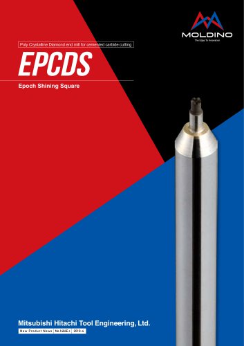 EPCDS
EPCDS4 Pages
 Epoch CFRP series
6 Pages
 EPSM-PN/ EPSW-PN
32 Pages
 GALLEA series
24 Pages
 WHMB-TH
12 Pages
 EMBE-ATH/EMBPE-ATH
16 Pages
 ETR(P)-TH,ETM(LN/P)-TH
16 Pages
 EPDRE-ATH
24 Pages
 CBN-EHB
12 Pages
 EHHBE-TH3
8 Pages
 TD6N type
12 Pages
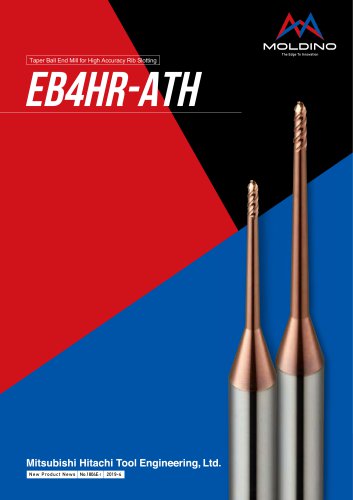 EB4HR-ATH
12 Pages
 EHX
EHX12 Pages
 EPHB-PN
8 Pages
 EHHRE-TH3
8 Pages
 EDT
EDT16 Pages
 EHSE-TH
8 Pages
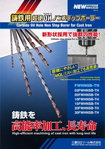 NSB
NSB12 Pages
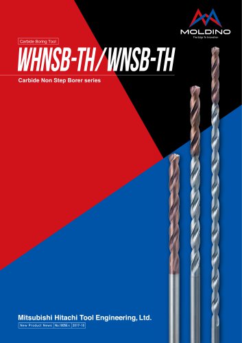 WHNSB-TH
20 Pages
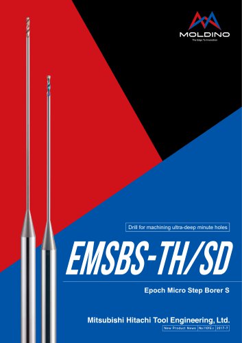 EMSBS
EMSBS8 Pages
 Ball Precision F ABPF type
16 Pages
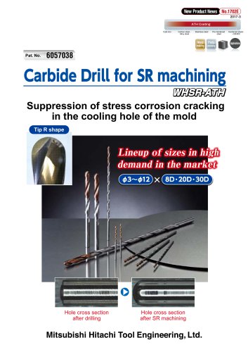 Carbide Drill for SR machining
12 Pages
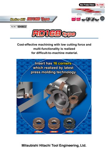 Radius Mill RD16B Type
8 Pages
 GS4TN type
4 Pages
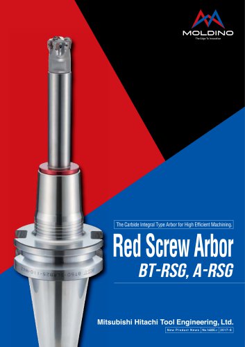 Red Screw Arbor
8 Pages
 ABP4F
ABP4F8 Pages
 EPDBE-PN/ATH EPDSE-PN/ATH
32 Pages
 EPDBEH-TH3
20 Pages
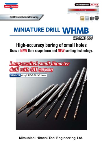 MINIATURE DRILL WHMB
8 Pages
 Epoch ® Combination Rib Ball
8 Pages
 PRODUCTS CATALOGUE 2015 - 2016
1070 Pages
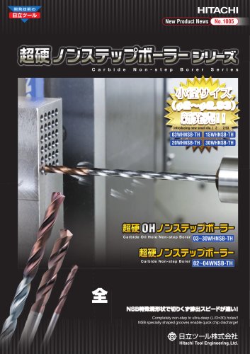
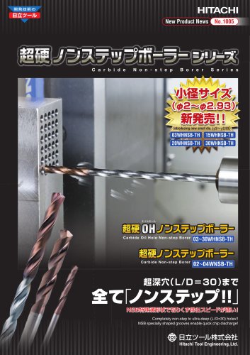 Carbide Non Step Borer series
28 Pages
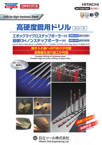 Drills for High-hardness Steels
16 Pages
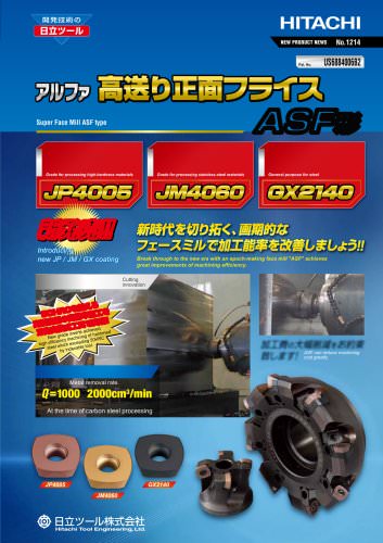 Face Mill : ASF type
8 Pages
 Face Mill : AFE45 type
8 Pages
 Ball Precision F : ABPF type
16 Pages
 Ball End Mill : ASB type
8 Pages
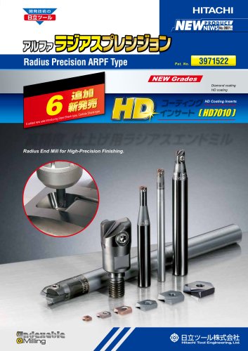 Radius Precision : ARPF type
12 Pages
 Polish Mill V Type : ASPV Type
20 Pages
 Roughing End Mill : AME Type
12 Pages
 Radius Mill : AR type
20 Pages
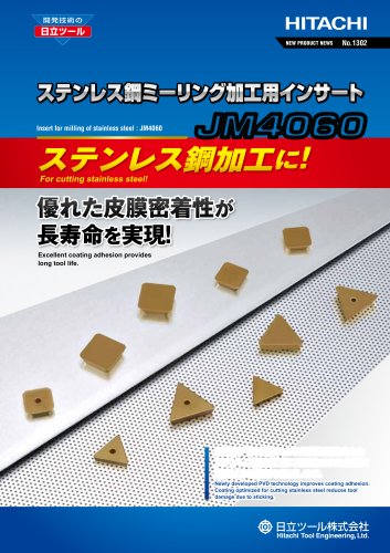 JM4060
4 Pages
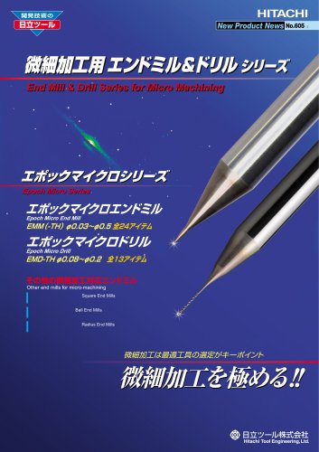 Epoch Micro?End Mill TH : EMM-TH
24 Pages
 Epoch Deep Radius Evolution
24 Pages
 Epoch Deep Ball Evolution Hard
16 Pages
 Epoch Micro Drill?EMD
24 Pages
 Radius Mill : ASR type
20 Pages
 Super Excellent MINI : ASM type
12 Pages
 Epoch "Mirus" Series
12 Pages
 Epoch G Turbo
8 Pages
 Roughing End Mill AME Type
12 Pages
 Z Plunging Borer?ZPB-TH
4 Pages
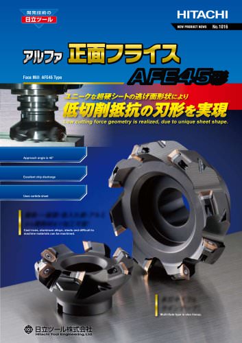 Face Mill AFE45
8 Pages
 Epoch Micro Step Borer S
8 Pages











Archived catalogs
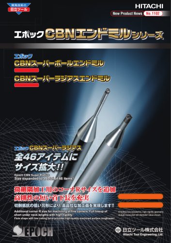 Epoch CBN End Mill series
16 Pages
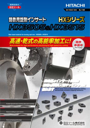 HX3505 & HX3515
6 Pages
 GX2140
4 Pages
 Epoch "Panacea"
16 Pages
 Epoch Deep Evolution series
24 Pages
 Epoch SUS End Mill series
32 Pages
 Epoch Pencil Deep Ball Evolution
20 Pages
 Epoch Deep Radius F
12 Pages
 Re-grinding & Re-coating
20 Pages
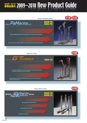 2009-2010 New Products Guide
5 Pages
 Micro Series for Micro Machining
14 Pages
 Milling Inserts
16 Pages
 Indexable Tools
160 Pages
 Threading Tools
6 Pages
 HSS End Mills
98 Pages
 Reamers
16 Pages
 Cutters
10 Pages
 CBN End Mills
20 Pages
 Surface Treatment Tribec
8 Pages
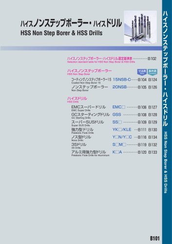 HSS Non Step Borer
36 Pages
 Carbide End Mills
280 Pages


- Milling tool
- Chuck
- Solid milling cutter
- Drilling tool
- Steel milling cutter
- Milling tool with replaceable insert
- Solid drill bit
- Metal milling cutter
- Clamping milling cutter
- Milling cutter with cylindrical shank
- End mill
- Cast iron milling cutter
- Face milling cutter
- Shell-end milling cutter
- Indexable insert milling cutter
- Ball nose milling cutter
- Cutting milling cutter
- Corner radius milling cutter
- Coated milling cutter
- High-performance milling cutter