EPDRE-ATH
1 /24Pages

EPDRE-ATH
1 /24Pages
Catalog excerpts
EPDRE-ATH Epoch Deep Radius Evolution
Open the catalog to page 1
Minimum corner R size of 0.02mm also in lineup! Carbon steel Stainless steel Pre-hardened Alloy steel Tool steel steel EPDRE-ATH Parts processing Mold making Improved heat-resistant coating Features and characteristics Hardness and oxidation resistance of TH coatings is further improved. Enables longer life and higher efficient when cutting high-hardness materials. (Si nano composite coating with finer crystal particles) Exhibits amazing performance when cutting high-hardness materials (55HRC or higher) Cold-worked die steel, HSS, tool steel. Long life for both dry cutting and wet cutting Guaranteed...
Open the catalog to page 2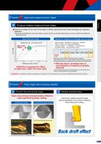
Improved compound neck shape Employs reliable compound neck shape ● Compound shape of tool neck R and taper is further improved to both resist breakage and suppress Static load test results oad 65 Testing tool size φ1×Under neck 6 Convent Conventi al ne sh p Convent onal neck shape Conventional neck shape o en e l Work material:SUS420J2H(Hardness:52HRC) Tool dia.: φ1(r 0.2)×Under neck length10 Cutting condition:n =12800min-1 v f =200mm/min∼ Dry with Air blow ap×ae=0.02mm×1mm Deflection amount【mm】 Deflection suppression effect is high even under the same load. Although the feed rate for the standard...
Open the catalog to page 3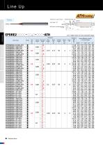
Tolerance on Corner radius r : ±0.005mm(Central axis) Back taper on peripheral edge: -1.5—6° EPDRE2 ATH 0 4 or higher does not have backdraft shape.
Open the catalog to page 4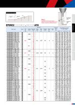
EPDRE2 ATH [Note] The effective under-neck length is different from Epoch Deep Radius EPDR. Please recheck the interference region.
Open the catalog to page 5
Tolerance on Corner radius r : ±0.005mm(Central axis) EPDRE2 ATH 0 4 or higher does not have backdraft shape.
Open the catalog to page 6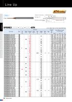
Tolerance on Corner radius r : ±0.005mm(Central axis) EPDRE2 ATH 0 4 or higher does not have backdraft shape.
Open the catalog to page 8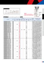
EPDRE2 ATH [Note] The effective under-neck length is different from Epoch Deep Radius EPDR. Please recheck the interference region.
Open the catalog to page 9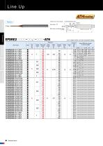
Line Up coating 2 Flutes φD c Back taper on peripheral edge : 1.5~6° High efficiency cutting cutting condition High efficiencycondition High accuracy cutting cutting condition High accuracycondition Technical Data Technical Data ●:Stocked Items. Corner Under neck radius length Flute length φ 4 or higher does not have backdraft shape. Neck dia. Overall length Size(mm) Item Code Tolerance on Corner radius r :±0.005mm(Central axis) Interference Angle Actual Effective Length in Incline Angles 14.08 14.72 16.23 18.64 19.51 No interference 23.20 24.30 No interference 34.61 No interference No interference...
Open the catalog to page 10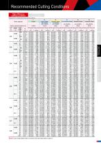
Please refer to P.16 about high accuracy cutting conditions [Note] Upon usage, please refer to comments and notes below table on page 15.
Open the catalog to page 11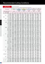
Please refer to P.16 about high accuracy cutting conditions
Open the catalog to page 12
[Note] Upon usage, please refer to comments and notes below table on page 15.
Open the catalog to page 13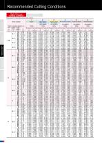
High efficiency cuttiing condition Please refer to P.16 about high accuracy cutting conditions
Open the catalog to page 14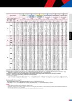
^(1) ap is shown as the criteria for Group 2 workpieces. For other groups, adjust the cutting depth according to the cutting depth factors in the above table. ^(2) When performing cutting where cutting chips may cause clogging, such as for rib cutting, blind grooves, etc., cutting depth setting should be set by multiplying a cutting depth factor to calculate the cutting depth amount, and this amount should then be reduced to 80% of the calculated value. ^(3) Adjust by setting ae to (5 or less)x(ap)x(cutting depth ratio). When performing finishing cutting, calculate the theoretical cusp height...
Open the catalog to page 15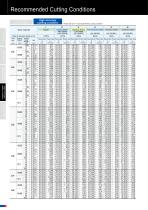
Please refer to P.11 about high efficiency cutting conditions
Open the catalog to page 16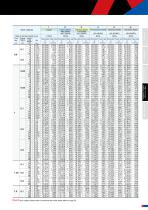
[Note] Upon usage, please refer to comments and notes below table on page 20.
Open the catalog to page 17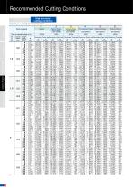
Please refer to P.11 about high efficiency cutting conditions
Open the catalog to page 18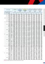
Work material [Note] Jpon usage, please refer to comments and notes below table on page 20.
Open the catalog to page 19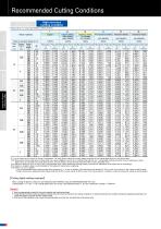
Please refer to P.11 about high efficiency cutting conditions ^(1) ap is shown as the criteria for Group 2 workpieces. For other groups, adjust the cutting depth according to the cutting depth factors in the above table. ^(2) When performing cutting where cutting chips may cause clogging, such as for rib cutting, blind grooves, etc., cutting depth setting should be set by multiplying a cutting depth factor to calculate the cutting depth amount, and this amount should then be reduced to 80% of the calculated value. ^(3) Adjust by setting ae to (5 or less)x(ap)x(cutting depth ratio). When performing...
Open the catalog to page 20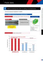
Field data Stable processing even when rib slotting in enclosed areas. Features This is amazing! Point 1 Good breakage resistance! Stabilized cutting performance! Conventional radius end mill 25mm Stable processing is possible to depths of 10mm. Deeper rib slotting achieved! Processing to final depth was possible for all three tools. Technical Data This is amazing! Point 2 High accuracy cutting condition High efficiency cutting condition Target depth Broken Broken
Open the catalog to page 21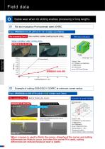
Field data Stable wear when rib slotting enables processing of long lengths. Features This is amazing! Point 1 Wear condition is stable, enabling long-life cutting. Wear condition after cutting 40m EPDRE2010-10-01-ATH High efficiency cutting condition High accuracy cutting condition Technical Data 02 Example of cutting SUS420J2Ⓗ 52HRC at minimum corner radius. Tool:EPDRE2004-2-002-ATH (φ0.4×r 0.02×Under neck 2mm) This is amazing! Point 2 Ideal for finishing tiny corners Conventional Square End Mill Evaluation of corner finishing Work observation point Flute tip edge line before cutting Wear...
Open the catalog to page 22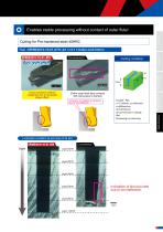
Enables stable processing without contact of outer flute! Features Cutting for Pre-hardened steel 40HRC Tool:EPDRE2010-10-01-ATH (φ1×r 0.1×Under neck10mm) Conventional A Cutting condition Back draft effect Entire outer flank face contacts with work-piece to fracture Inclination of chattering vibrations due to tool deflection. Technical Data Coolant:Wet n=17,350min-1(vc=54m/min) v f =655mm/min (fz=0.018mm/t) ap×ae=0.012mm× Change Wet Processing by contouring High accuracy cutting condition Good conditions without chattering due to backdraft shape effect. High efficiency cutting condition Inclination...
Open the catalog to page 23All MOLDINO Tool Engineering Europe GmbH catalogs and technical brochures
 CUTTING TOOLS PRODUCTS CATALOGUE
1364 Pages
 CUTTING TOOLS PRODUCTS CATALOGUE
1056 Pages
 CBN-EPSB/CBN-EPSR
16 Pages
 EPBTS
EPBTS12 Pages
 EMXR
EMXR16 Pages
 EMXA
EMXA12 Pages
 EPDRF-TH
12 Pages
 EPDBPE-ATH
20 Pages
 Epoch TH Power Mill
12 Pages
 Radius Precision ARPF
20 Pages
 Carbide Thread Mill series
16 Pages
 SCE-R
SCE-R6 Pages
 RV type
12 Pages
 ABPFN type
6 Pages
 TD4N type
8 Pages
 EHHB-ATH
8 Pages
 EPCDS
EPCDS4 Pages
 Epoch CFRP series
6 Pages
 EPSM-PN/ EPSW-PN
32 Pages
 GALLEA series
24 Pages
 WHMB-TH
12 Pages
 EMBE-ATH/EMBPE-ATH
16 Pages
 ETR(P)-TH,ETM(LN/P)-TH
16 Pages
 CBN-EHB
12 Pages
 EHHBE-TH3
8 Pages
 TD6N type
12 Pages
 EB4HR-ATH
12 Pages
 EHX
EHX12 Pages
 EPHB-PN
8 Pages
 EHHRE-TH3
8 Pages
 EDT
EDT16 Pages
 EHSE-TH
8 Pages
 NSB
NSB12 Pages
 WHNSB-TH
20 Pages
 EMSBS
EMSBS8 Pages
 Ball Precision F ABPF type
16 Pages
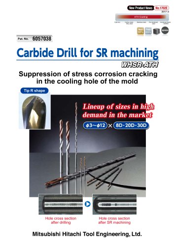 Carbide Drill for SR machining
12 Pages
 Radius Mill RD16B Type
8 Pages
 GS4TN type
4 Pages
 Red Screw Arbor
8 Pages
 ABP4F
ABP4F8 Pages
 EPDBE-PN/ATH EPDSE-PN/ATH
32 Pages
 EPDBEH-TH3
20 Pages
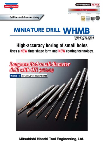 MINIATURE DRILL WHMB
8 Pages
 Epoch ® Combination Rib Ball
8 Pages
 PRODUCTS CATALOGUE 2015 - 2016
1070 Pages
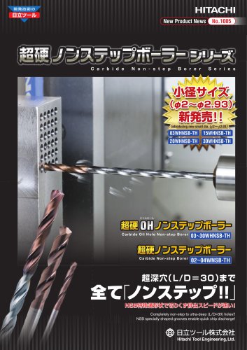 Carbide Non Step Borer series
28 Pages
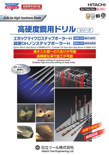 Drills for High-hardness Steels
16 Pages
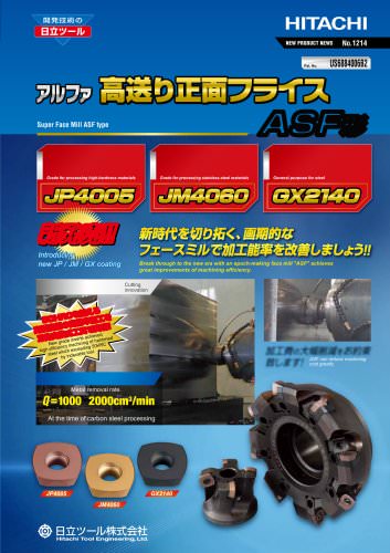 Face Mill : ASF type
8 Pages
 Face Mill : AFE45 type
8 Pages
 Ball Precision F : ABPF type
16 Pages
 Ball End Mill : ASB type
8 Pages
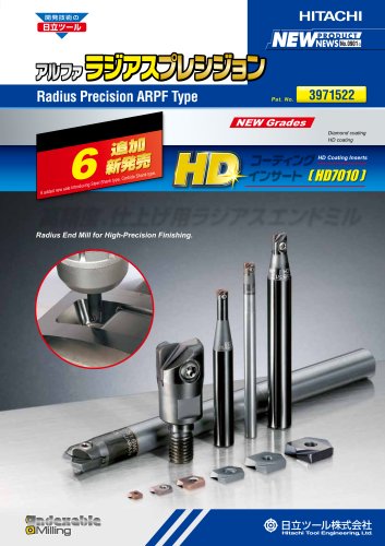 Radius Precision : ARPF type
12 Pages
 Polish Mill V Type : ASPV Type
20 Pages
 Roughing End Mill : AME Type
12 Pages
 Radius Mill : AR type
20 Pages
 JM4060
4 Pages
 Epoch Micro?End Mill TH : EMM-TH
24 Pages
 Epoch Deep Radius Evolution
24 Pages
 Epoch Deep Ball Evolution Hard
16 Pages
 Epoch Micro Drill?EMD
24 Pages
 Radius Mill : ASR type
20 Pages
 Super Excellent MINI : ASM type
12 Pages
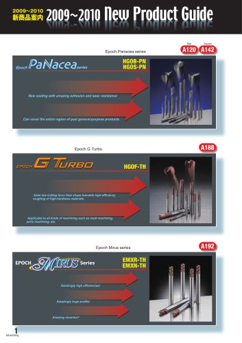
 Epoch "Mirus" Series
12 Pages
 Epoch G Turbo
8 Pages
 Roughing End Mill AME Type
12 Pages
 Z Plunging Borer?ZPB-TH
4 Pages
 Face Mill AFE45
8 Pages
 Epoch Micro Step Borer S
8 Pages


Archived catalogs
 Epoch CBN End Mill series
16 Pages
 HX3505 & HX3515
6 Pages
 GX2140
4 Pages
 Epoch "Panacea"
16 Pages
 Epoch Deep Evolution series
24 Pages
 Epoch SUS End Mill series
32 Pages
 Epoch Pencil Deep Ball Evolution
20 Pages
 Epoch Deep Radius F
12 Pages
 Re-grinding & Re-coating
20 Pages
 2009-2010 New Products Guide
5 Pages
 Micro Series for Micro Machining
14 Pages
 Milling Inserts
16 Pages
 Indexable Tools
160 Pages
 Threading Tools
6 Pages
 Turning Inserts
44 Pages
 HSS End Mills
98 Pages
 Reamers
16 Pages
 Cutters
10 Pages
 CBN End Mills
20 Pages
 Surface Treatment Tribec
8 Pages
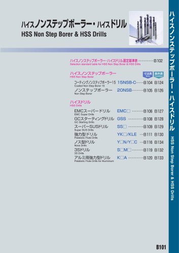 HSS Non Step Borer
36 Pages
 Carbide End Mills
280 Pages


- Milling tool
- Chuck
- Solid milling cutter
- Drilling tool
- Milling tool with replaceable insert
- Steel milling cutter
- Metal milling cutter
- Solid drill bit
- Clamping milling cutter
- Milling cutter with cylindrical shank
- Face milling cutter
- Shell-end milling cutter
- Cast iron milling cutter
- Indexable insert milling cutter
- Ball nose milling cutter
- Cutting milling cutter
- Corner radius milling cutter
- High-performance milling cutter
- Shoulder milling cutter