

Magnetic powder brakes and coupling

Magnetic powder brakes and coupling
This document provides comprehensive technical information on magnetic particle brakes and clutches used in industrial applications. These devices offer torque ranging from 0.2 to 1000 Nm, ensuring noiseless operation with torque directly proportional to the applied current.
The magnetic particle brake or clutch features two independently rotating rotors. The outer rotor contains an electrical coil that magnetizes particles in the air gap when powered by DC current, forming a particle chain whose stiffness varies with the current, thus creating a braking torque proportional to the current.
- Noiseless operation
- Torque directly proportional to current
- Torque independent of rotational speed above 40 rpm
- Robust design suitable for continuous slip
- Wide torque adjustment range (1:50)
- Clutch and coupling operations
- Braking
- Torque control and limiting
- Tension control in spooling and unspooling
- Controlled braking and acceleration of inertial masses
The document includes detailed specifications for various models, covering nominal torque, minimal torque, coil resistance, rated current, rotor inertia, and operational temperature ranges. It also provides recommended mounting principles, emphasizing stress-free installation and horizontal operation.
- Mounting should be stress-free, using flexible couplings if necessary.
- Devices are designed for horizontal operation with speeds between 60 and 3000 rpm.
The document lists additional components such as torque limiters, flexible couplings, power supply units, digital controllers, ultrasonic sensors, force measuring rollers, torque transducers, and shaft lockings, along with their specifications and applications.
The document provides detailed technical specifications for various mechanical components, including brakes, clutches, and cooling units. Key parameters such as nominal torque, minimal torque, coil resistance, rated current, rotor inertia, and operational temperatures are outlined for each component.
The FRATO 10001 series includes through shaft brakes with specifications such as nominal torque, minimal torque, coil resistance, and rated current. The document also details the maximum and minimum operational speeds, weight, and heat dissipation capabilities.
Various cooling units, including radial and axial fan cooling units, are described. Specifications include voltage, frequency, power consumption, weight, sound level, and protection level. The document provides mounting instructions and highlights the importance of stress-free installation.
The EFAS and EAT series clutches are detailed, with specifications on nominal and minimal torque, coil resistance, rated current, rotor inertia, and operational speeds. The document emphasizes the need for proper mounting without stress and the use of flexible couplings if necessary.
Instructions for mounting fan cooling units and clutches are provided, emphasizing the importance of correct installation to ensure optimal performance.
Tables and diagrams within the document provide visual representation of torque versus current for various components, aiding in the understanding of performance characteristics under different operational conditions.
The document provides technical specifications for various mechanical components, including torque limiters and flexible couplings. Key parameters include nominal torque, minimal torque, coil resistance, rated current, rotor inertia, and operational temperature ranges. The components are designed for specific rotational speeds and heat dissipation capabilities.
Mounting instructions emphasize stress-free installation, recommending the use of flexible couplings if necessary. The devices are primarily designed for horizontal shaft orientation, with specified speed ranges and heat dissipation limits.
The document outlines the importance of adhering to specified power dissipation limits to ensure optimal performance and longevity of the components. It also highlights the need for proper alignment and stress-free mounting to prevent operational issues.
Torque limiters are used in various industries, including aviation, data processing, medical devices, and machinery. They provide steady braking, torque limitation, and protection for transmission parts.
The torque limiters utilize magnetic particle technology, replacing electric coils with permanent magnets to control torque through a magnetic field. The torque remains constant regardless of rotational speed, adjustable via a "shunt" ring.
The tables provide detailed specifications for different types of torque limiters, including transmission torque ranges, heat dissipation values, and rotor inertia. Graphs illustrate the relationship between torque and current for various models.
Ensure that the power dissipation does not exceed the specified limits. The maximum power is three times the power dissipation value. Proper installation and adherence to operational guidelines are crucial for maintaining device performance and safety.
The document outlines the specifications for a current-controlled power supply and digital controller systems. Key specifications include input and output voltage ranges, overload protection, and temperature monitoring. The power supply is designed to switch off during thermal overload and can be reset after a cooldown period. It complies with standards EN 60950 and EN 55022 B.
The power supply allows for current and torque control via external control tension (0-10 V) or an internal potentiometer. Switching between different output currents is possible for applications like immediate braking during disturbances. The digital controller features advanced regulation techniques, including automatic PID parameter adjustments, closed and open loop modes, and inertia compensation.
The DGT 300 digital controller offers user-friendly features such as selectable languages and units, easy setup via Windows PC software, and a backlit display. It supports universal load cell inputs and direct input for diameter information using various sensors.
The document describes tension control systems for maintaining web tension accuracy. These systems use sensors to measure roll diameter and adjust torque accordingly. Closed loop solutions include position control using a dancer roll and force control using load cells.
Specifications for ultrasonic sensors include sensing range, repeat accuracy, and response times. The sensors are designed for robust performance with features like short circuit and reverse polarity protection.
The RMGZ 100 series force measuring roller is used for tension measurement in wire and cable materials. It features a 10-fold overload protection and requires no recalibration, utilizing a flexion principle with strain gauges for accurate tension measurement.
The document describes the principle of force measurement using a beam subjected to bending stress. Four foil-type strain gauges configured in a full Wheatstone bridge measure the bending and material tension. The position of the red point indicates the direction of force application, with positive values resulting when the force acts in the direction of the red point.
Various sensor types are listed with specifications such as nominal force, load rating, speed limit, and weight. Options include right angle connectors (H14) and extended temperature ranges (H16). The sensors are made of steel with aluminum mounting brackets and are sealed against dust (IP40).
Designed for material tension measurement on rollers with rotating shafts, the C 203 series allows easy roller changes in automated processes. The sensors use a dual flexion beam design with mechanical overload protection, ensuring high accuracy and reliability without frequent recalibration. They are made of stainless steel with an aluminum cover.
Details include nominal torque, spring rate, maximum revolution, and thrust load. The transducers have a high accuracy class and are protected against overload. They feature a cut-off frequency of 1 kHz and are protected to IP50 standards.
The unit supports up to 10 sensor parameter sets, a current loop input, and an RS-232 interface. It can log up to 3000 measurements and supports fast measurement rates. The unit operates on mains, battery, or accumulator power and displays physical units.
Includes simple shaft locks made of stainless steel for non-hardened shafts and axial fast action clamping systems for hardened shafts. The systems allow for variable tensioning forces and easy release.
Guidelines for calculating brake or clutch dimensions based on torque, power loss, maximum speed, and response time. The document emphasizes the preference for external drive in magnetic powder clutches.
The document outlines the specifications and design recommendations for magnetic particle brakes and clutches. It emphasizes the importance of using an external drive for better powder distribution and mandates it when the clutch operates in a disengaged state during operation. The installation should preferably be on a horizontal axis, and if vertical, a residual magnetization of about 10% should be maintained.
The bore of the magnetic particle clutch is machined to DIN/ISO H8 standards. Maximum permissible speeds are 3000 rpm for units up to 200 Nm and approximately 1500 rpm for larger types. Torque is independent of speed from about 30 rpm.
During installation, ensure correct mechanical alignment and use elastic connections to accommodate deflection. Before initial operation and after long periods of inactivity, the unit should run at 100-300 rpm for about 5 minutes, switching on and off approximately 30 times to ensure even powder distribution. The units are lubricated for life and require no additional lubrication. In aggressive environments, a protective cover is recommended, provided cooling is sufficient.
The units are virtually maintenance-free except for the magnetic powder, which has a lifespan of 2000 to 5000 hours. Wear is indicated by a decrease in torque, requiring occasional adjustment. When the excitation setting increases by about 30%, the powder should be replaced.
Selection should consider maximum required torque, power dissipation, rpm speed, and reaction time. Calculations for torque and acceleration of inertia are provided, emphasizing the need to know the inertia and time for acceleration or braking.
The document provides contact details for various international representatives and agents for further assistance and product inquiries.
Catalog excerpts
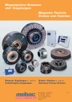
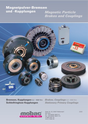
Magnetpulver-Bremsen und -Kupplungen Magnetic Particle Brakes and Clutches Bremsen, Kupplungen 0,2 - 1000 Nm Schleifringlose Kupplungen Brakes, Clutches 0.2 -1000 Nm Stationary Primary Clutches
Open the catalog to page 1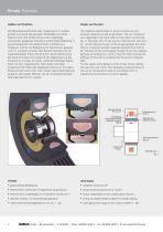
Prinzip Principle Die Magnetpulver-Bremse oder -Kupplung ist im Aufbau einfach und erzielt bei geringem Platzbedarf ein hohes Drehmoment. Die Einheit ist aus zwei unabhängig voneinander gelagerten Rotoren A und B (siehe Abbildung 1) zusammengesetzt. Der äußere Rotor A enthält eine Ringspule, welche zur Betätigung mit Gleichstrom gespeist wird. Im Luftspalt zwischen den Rotoren befindet sich ein magnetisierbares Pulver (ferro/chrom). Durch Bestromung der Spule formieren sich aufgrund der Magnetisierung die Pulverkörner zu einer Art Kette, wobei die Steifigkeit dieser Kette mit dem magnetischen...
Open the catalog to page 2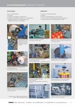
Anwendungsbeispiele Application Examples Ein- und Auskuppeln Bremsen Drehmomentregelung, -begrenzung Zugspannungsregelung beim Auf- und Abwickeln gezieltes Bremsen und Ingangsetzen von Trägheitsmomenten und Massen clutch and coupling operations braking torque control applications, torque limiting tension control on spooling and unspooling application calculated braking, with accelerating of inertias Prüfstand für LKW-Hinterachsen Test bench for truck axles Zugregelung einer Stempelschneidmaschine Closed loop tension control & regulation on a die cutting machine Automatischer Spleißdrehkopf einer...
Open the catalog to page 3
Inhaltsverzeichnis Table of Contents Bremsen Brakes External Shaft Brakes Nenn moment Nominal torque Gleichstrom Gewicht Rated Current Weight Empfohlener Einbau / Recommended mounting Through Shaft Brakes with water cooling with water cooling VR 1200 Radiallufter / Radial Fan Cooling Unit Nur Lufter/ Cooling fan units only Empfohlener Einbau / Recommended mounting 4 fflObaC GmbH ■ BunsenstraRe 1 ■ D-24145 Kiel ■ Phone+49 (0)431-65 02 77 ■ Fax+49 (0)431-65 05 11 ■ E-mail: [email protected]
Open the catalog to page 4
Inhaltsverzeichnis Table of Contents Kupplungen Clutches Nominal torque Rated Current Kupplungen ohne Schleifringubertrager Stationary Primary Clutches Empfohlener Einbau / Recommended mounting Through Shaft Clutches with transmitting slip ring Empfohlener Einbau / Recommended mounting Drehm omentbegrenzer Torque Limiters Drehmomentbegrenzer / Torque Limiters Wellen-Klauenkupplungen (WKK) Flexible Coupling (WKK) 57 Netzteil Power Supply Unit 58 - 59 Digitale Steuerung DGT 300 Digital Controller DGT 300 60 - 62 Ultraschallsensor Ultrasonic sensors 63 Kraftmessrolle/-aufnehmer Force Measuring Roller/Sensor...
Open the catalog to page 5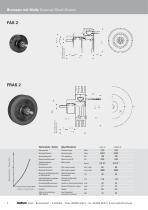
Bremsen mit Welle External Shaft Brakes Technische Daten Nominal torque Kleinstes Moment Minimal torque Coil resistance Trägheitsmoment Rotorgewicht Rotor inertia Minimale Drehzahl Maximale Drehzahl Maximale Außentemperatur im Dauerbetrieb Rated outside body temperature Höchstzulässige kurzzeitige Betriebstemperatur Ultimate outside body temperature Switch-on time/nominal torque (ms) Switch-off time/min. torque Heat dissipation continuous sustained
Open the catalog to page 6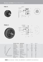
Bremsen mit Welle External Shaft Brakes 3 Bohrungen M4 bei 120° auf Ø 50, max. Tiefe 10 3 holes M4 at 120° on Ø 50 max. depth 10 Bohrung Ø 3,05 hole Ø 3.05 Technische Daten Nominal torque Kleinstes Moment Minimal torque Coil resistance Trägheitsmoment Rotorgewicht Rotor inertia Minimale Drehzahl Maximale Drehzahl Maximale Außentemperatur im Dauerbetrieb Rated outside body temperature Höchstzulässige kurzzeitige Betriebstemperatur Ultimate outside body temperature Switch-on time/nominal torque (ms) Switch-off time/min. torque Heat dissipation continuous sustained
Open the catalog to page 7
Bremsen mit Welle External Shaft Brakes Technische Daten Nominal torque Kleinstes Moment Minimal torque Coil resistance Trägheitsmoment Rotorgewicht Rotor inertia Minimale Drehzahl Maximale Drehzahl Maximale Außentemperatur im Dauerbetrieb Rated outside body temperature Höchstzulässige kurzzeitige Betriebstemperatur Ultimate outside body temperature Switch-on time/nominal torque (ms) Switch-off time/min. torque Heat dissipation continuous sustained
Open the catalog to page 8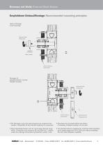
Bremsen mit Welle External Shaft Brakes Empfohlener Einbau/Montage Recommended mounting principles übliche Montage In line mounting Rotierende Welle Rotating shaft Elastische Ankopplung Elastic coupling Externe Halterung External frame Montage für parallelversetzten Antrieb Parallel mounting Rotierende Welle Rotating shaft Externe Halterung External frame (Timing) belt drive • Die Montage muss ohne jede Verspannung vorgenommen werden, nötigenfalls ist eine flexible Kupplung zu verwenden. • Mounting must be made without any stress. If necessary a flexible coupling is to be used. • Diese Standardeinheiten...
Open the catalog to page 9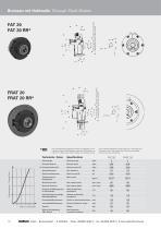
Bremsen mit Hohlwelle Through Shaft Brakes Die so bezeichnete baugleiche Einheit ist ausgeführt mit remanentem Rotor. Dies bedeutet, dass auch Drehzahlen von ≥ 40 min-1 möglich sind und der Einbau mit vertikaler Achse. The so defined identically constructed unit is executed with a remanent rotor. This means that ≥ 40 rpm are possible and the use with vertical axis. Technische Daten Nominal torque Kleinstes Moment Minimal torque Coil resistance Trägheitsmoment Rotorgewicht Rotor inertia Minimale Drehzahl Maximale Drehzahl Maximale Außentemperatur im Dauerbetrieb Rated outside body temperature...
Open the catalog to page 10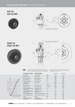
Bremsen mit Hohlwelle Through Shaft Brakes Die so bezeichnete baugleiche Einheit ist ausgeführt mit remanentem Rotor. Dies bedeutet, dass auch Drehzahlen von ≥ 40 min-1 möglich sind und der Einbau mit vertikaler Achse. The so defined identically constructed unit is executed with a remanent rotor. This means that ≥ 40 rpm are possible and the use with vertical axis. Technische Daten Nominal torque Kleinstes Moment Minimal torque Coil resistance Trägheitsmoment Rotorgewicht Rotor inertia Minimale Drehzahl Maximale Drehzahl Maximale Außentemperatur im Dauerbetrieb Rated outside body temperature...
Open the catalog to page 11All Mobac catalogs and technical brochures
 Magnetic Co-Axial Couplings
5 Pages
 Magnetic Disc Couplings
7 Pages
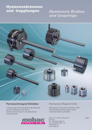 Hysteresis Brakes and Couplings
28 Pages
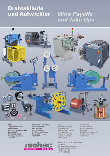 Wire Payoffs and Takes Ups
90 Pages
 General catalogue
232 Pages
 Wire Payoffs - Winder
68 Pages
 Magnetic Disc Couplings
4 Pages



- DC power supply
- AC/DC power supply
- Friction brake
- Tabletop power supply
- Torque coupling
- Transmission coupling
- Electromagnetic brake
- Hand truck
- Friction clutch
- Adjustable stand
- Automatic winder
- Manual unwinder
- Custom-made coupling
- Handling hand truck
- Disc clutch
- Industrial accumulator
- Wire payout
- Cable support
- Folding hand truck