Double Float Bleed Valves
1 /2Pages

Double Float Bleed Valves
1 /2Pages
Catalog excerpts
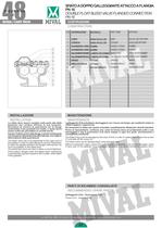
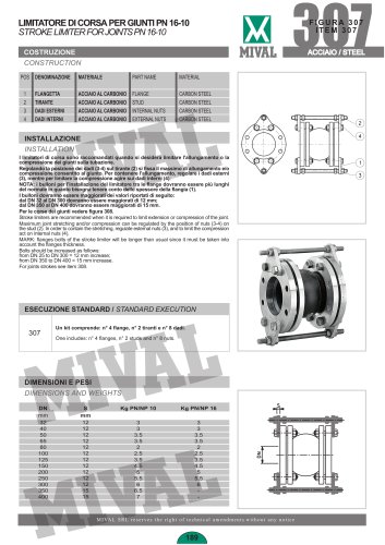
48 SFIATO A DOPPIO GALLEGGIANTE ATTACCO A FLANGIA PN 16 DOUBLE FLOAT BLEED VALVE FLANGED CONNECTION PN 16 FIGURA 48 GHISA / CAST IRON COSTRUZIONE CONSTRUCTION POS DENOMINAZIONE 1 2 3 4 5 6 7 8 9 INSTALLAZIONE INSTALLATION Lo sfiato deve essere montato sulla parte alta delle tubazioni per rendere efficace la sua funzione. Ricordarsi di inserire le guarnizioni tra le flange centrandole il più possibile sul risalto, il quale dovrà essere pulito per permettere la corretta tenuta. Inserire i bulloni nei fori delle flange e serrarli mantenendo una frequenza diametralmente alternata (per una migliore deformazione delle guarnizioni). The bleed valve has to be assembled at the upper part of the pipeline in order to make efficient its service. Remember to insert the gaskets between the flanges centring them as much as possible on the raised face. The raised face has to be clean to allow a correct tightness. Fit the bolts in flanges holes and tighten them maintaining a diametrically opposed sequence (for a better deformation of the gaskets). CORPO COPERCHI GUARNIZIONE O-RING GUARNIZIONE O-RING GALLEGGIANTEGRANDE GALLEGGIANTEPICCOLO ORIFIZIO ANELLO DI TENUTA VITI MATERIALE PART NAME MATERIAL GHISA EN-GJL-250 GHISA EN-GJL-250 GOMMA GOMMA LAMIERA RIV.GOMMA LAMIERA RIV.GOMMA OTTONE OTTONE ACCIAIO ZINCATO BODY COVERS GASKET O-RING GASKET O-RING MAIN FLOAT SECONDARY FLOAT ORIFICE SEALING RING SCREWS EN-GJL-250 CAST IRON EN-GJL-250 CAST IRON RUBBER RUBBER STEEL PLATE + RUBBER STEEL PLATE + RUBBER BRASS BRASS ZINC PLATED STEEL MANUTENZIONE MAINTENANCE I galleggianti (5-6) potrebbero danneggiarsi con l'usura nel tempo, per sostituirli svitare le viti(9) e togliere i coperchi (2). Se necessario lo sfiato può essere smontato completamente utilizzando utensili standard. Prima di riassemblarlo, verificare che i piani di tenuta siano accuratamente puliti e non danneggiati e che le guarnizioni (3-4) siano integre in ogni loro parte; diversamente è consigliabile sostituirle. The floats (5-6) could be damaged by the wear of time; in order to replace them loosen the screws (7) and take off the covers (2). The bleed valve can be disassembled using standard tools. Before to assemble it again, check if the sealing seats are carefully clean and not damaged, check if each part of the gaskets (3-4) is integral; otherwise it is recommended to replace them. PARTI DI RICAMBIO CONSIGLIATE RECOMMENDED SPARE PARTS Galleggianti (5-6) - Guarnizioni (3-4) Floats (5-6) - Gaskets (3-4) L a M I VA L S R L s i r i s e r v a d i a p p o r t a r e m o d i f i c h e s e n z a a l c u n p r e a v v i s o 92
Open the catalog to page 1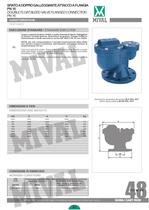
SFIATO A DOPPIO GALLEGGIANTE ATTACCO A FLANGIA PN 16 DOUBLE FLOAT BLEED VALVE FLANGED CONNECTION PN 16 CARATTERISTICHE FEATURES ESECUZIONE STANDARD / STANDARD EXECUTION Corpo e coperchi di ghisa. Orifizio e anello di tenuta di ottone. Galleggianti di lamiera rivestita gomma. Guarnizioni di gomma. Flangia dattacco dimensionata e forata secondo le norme EN 1092-2 PN 16 con risalto. 48 NOTA: per non compromettere il corretto funzionamento dello sfiato non devono esserci turbolenze nell'impianto; pressione minima di funzionamento 2/3 bar. Cast iron body and covers. Brass orifice and sealing ring....
Open the catalog to page 2All Mival catalogs and technical brochures
 CATALOGUE 2024
52 Pages
 346
3462 Pages
 Joint – Item 308 TIFQ
1 Page
 MIVAL Products
72 Pages
 Filtro raccoglitore
2 Pages
 Ball valve – Item 736
1 Page
 Ball valve – Item 737
1 Page
 Ball valve – Item 737/MF
1 Page
 Check valve – Item 57
2 Pages
 Check valve – Item 335
2 Pages
 Ball valve – Item 447
2 Pages
 Ball valve – Item 446
2 Pages
 Ball valve – Item 442
2 Pages
 Ball valve – Item 441
2 Pages
 Y strainer – Item 503
2 Pages
 Y strainer – Item 500
2 Pages
 Y strainer – Item 266
2 Pages
 Y strainer – Item 264
2 Pages
 Y strainer – Item 263 TIFQ
2 Pages
 Gate valve – Item 15
2 Pages
 Gate valve – Item 10/OR
2 Pages
 Gate valve – Item 10
2 Pages
 Bellows valve – Item 64
2 Pages
 Bellows valve – Item 61
2 Pages
 Bellows valve – Item 347
2 Pages
 Bellows valve – Item 63
2 Pages
 Bellows valve – Item 53
2 Pages
 54
542 Pages
 Bellows valve – Item 6
2 Pages
 Bellows valve – Item 51
2 Pages
 691
6911 Page
 266/25
2 Pages
 150
1502 Pages
 154
1542 Pages
 WAFER VALVE
12 Pages
 COMBO VALVE
20 Pages
 BALANCING VALVES
16 Pages


Archived catalogs
 MIVAL CATALOGUE EDITION 01/22
52 Pages
 PRODUCTS 2014
64 Pages
 flange gate valve
5 Pages
 bras gate valve
3 Pages
 wafer butterfly valve
5 Pages
 lug butterfly valve
5 Pages
 axial joint
2 Pages
 expansion joint
4 Pages
 ball check valve
5 Pages
 swing check valve
2 Pages
 cast iron ball valve
5 Pages
 swing check valve
5 Pages
 bleed valve
5 Pages
 balancing valve
2 Pages
 flow indicator
7 Pages
 holder valve
5 Pages
 3 way valve
2 Pages
 3 way valve
2 Pages
 Disk Check Valves
7 Pages
 ANSI series Check Valves
9 Pages
 Double Swing Check Valves
2 Pages
 Carbon steel level Gauges
5 Pages
 Brass level Gauges
2 Pages
 Discharge Valves
5 Pages
 Float Valves
2 Pages
 New Combo Valve
20 Pages
 ANSI series Gate Valves
9 Pages
 Antivibrating Joints
1 Page
 Axial Expansion Joints
2 Pages
 gate valve
5 Pages
 Simple Bleed Valves
5 Pages
 Bronze Balancing Valves
1 Page
 Three Ways Plug Cocks
2 Pages
 Brass Plug Cocks
1 Page
 Cast Iron Plug Cocks
2 Pages
 general catalogue
56 Pages
 Catalogue 2010
12 Pages
 Mival catalogue
28 Pages
 MIVAL VALVES
28 Pages