
Catalog excerpts
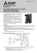
Drive Safety integrated AC servo amplifier Safety logic unit <MR-J3-D05> The MR-J3-DS Drive Safety integrated AC servo amplifier (SSCNET IE compatible) and MR-J3-D05 safety logic unit are newly added to Safety functions of the MR-J3-DS and MR-J3-D05 are certified for (Category 3) by a Certification Body (TUV Rheinland). As a safety function, MR-J3-DS has an integrated Safe torque off (STO) function. Safe stop 1 (SS1) function can be realized by combining MR-J3-DS with MR-J3-D05. These functions contribute to improvement of safety in the user's system, making it easy to obtain third-party certification. If MR-J3-DB is currently used in a user's system, it can be easily replaced by the MR-J3-DS since both of these servo amplifiers use the same cables and connectors. Also, the MR-J3-DS lineup contains fully closed loop control system versions. • MR-J3-DS and MR-J3-D05 meet IEC/EN 61508 SIL 2, EN 62061 SIL CL 2 and EN ISO 13849-1 PL d (Category 31 Only the Safe torque off (STO)*1 function is integrated into the MR-J3-DS. The MR^J3-D05 contains both Safe stop 1 (SS1) and Safe • User's system can satisfy stop category 0*2 by using the Safe torque off (STO) function*1. • User's system can satisfy stop category 0 and 1*2 by using the Safe torque off (STO) and Safe stop 1 (SS1) functions*1. • Mounting, wiring and connectors of MR^J3-DS are compatible with those of MR-J3-DB. Thus, MR-J3-DB can be easily replaced by the MR-J3-DS using the existing connections. The safety functions are accessible via the new CN8 connector on *1. Refer to EN IEC 61800-5-2 for details of Safe torque off (STO) and Safe stop 1 (SS1) functions. *2. Refer to EN IEC 60204-1 for details of stop category. System Configurations (example of using 2 systems of STO and SS1 functions) Safety logic unit Power supply Notes: 1. For prevention of electric shock during maintenance or for protection during servo amplifier fault, be sure to connect a magnetic contactor (MC) between the main power supply and L1, L2 and L3 of the servo amplifier or converter unit. 2. Connect the STO switch signal and forced stop 2 (EM2) signal in connector CN3 of the servo amplifier in addition to the connection with the safety logic unit (MR-J3-D05). 3. Safety logic unit (MR-J3-D05) has 2 independent systems (A-axis and B-axis). 4. All safety-related components such as relays, sensors, etc., must meet the applicable safety standards. 5. Perform risk assessment and safety level certification on the entire machine/system.
Open the catalog to page 1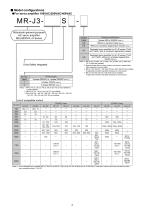
Model configurations Mitsubishi general-purpose^ Drive Safety integrated Notes: 1. Use a dedicated servo amplifier MR-J3-DS(4)-LR or MR-J3-DS(4)-LW for HF-JP11K1 M(4) and HF-JP15K1 M(4). These servo motors cannot be used with any other servo amplifiers without "-LR/-LW".
Open the catalog to page 2
Mitsubishi general-purpose\ Converter unit drive unit. List of compatible motors
Open the catalog to page 3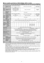
Servo amplifier specifications (100VAC/200VAC, 22kW or smaller) Servo amplifier model Voltage/frequency (Note 1, 2) Main circuit power supply Permissible voltage fluctuation Permissible frequency fluctuation Voltage/frequency Permissible voltage fluctuation Permissible frequency fluctuation Power (W) consumption Interface power supply Built-in regenerative Tolerable resistor regenerative External power (W) of regenerative regenerative resistor resistor (standard accessory) Control circuit power supply 24VDC±10% (required current capacity: 200mA (including CN8 connector signals) (Note 3)) -...
Open the catalog to page 4
Servo amplifier specifications (200VAC, 30kW or larger) Drive unit MR-J3-DU S Drive unit model Compatible converter unit model Main circuit power supply Control circuit power supply Voltage/frequency (Note 1) Permissible voltage fluctuation Permissible frequency fluctuation Voltage/frequency The drive unit’s main circuit power is supplied from the converter unit. Permissible voltage fluctuation Permissible frequency fluctuation Power consumption (W) Interface power supply ±5% maximum 45 24VDC±10% (required current capacity: 200mA (including CN8 connector signals) (Note 3)) Control system...
Open the catalog to page 5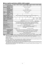
Servo amplifier specifications (400VAC, 22kW or smaller) Servo amplifier model Dynamic brake 24VDC±10% (required current capacity: 200mA (including CN8 connector signals) (Note 3)) 15 Sine-wave PWM control/current control system Built-in (Note 6, 8) External option Overcurrent shutdown, regeneration overvoltage shutdown, overload shutdown (electronic thermal), servo motor overheat protection, encoder fault protection, regeneration fault protection, undervoltage/sudden power outage protection, overspeed protection, excess error protection 20ms or less (STO input OFF → energy shut off) Safety...
Open the catalog to page 6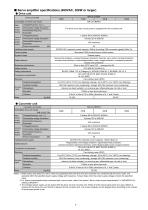
Servo amplifier specifications (400VAC, 30kW or larger) Drive unit MR-J3-DU S4 Drive unit model Compatible converter unit model Main circuit power supply Control circuit power supply Voltage/frequency (Note 1) Permissible voltage fluctuation Permissible frequency fluctuation Voltage/frequency The drive unit’s main circuit power is supplied from the converter unit. Permissible voltage fluctuation Permissible frequency fluctuation Power consumption (W) Interface power supply 1-phase 323 to 528VAC ±5% maximum 45 24VDC±10% (required current capacity: 200mA (including CN8 connector signals)...
Open the catalog to page 7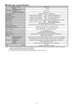
Safety logic unit specifications Safety logic unit model Control circuit power supply Voltage Permissible voltage fluctuation Required current capacity Compatible system 2 systems (A-axis, B-axis independent) Shut-off input 4 points (2 points x 2 systems) : source/sink compatible (Note 3) Shut-off release input 2 points (1 point x 2 systems) : source/sink compatible (Note 3) Feedback input 2 points (1 point x 2 systems) Input method Shut-off output Output method Response performance (when delay time is set to 0s) 20ms or less (STO input OFF → shut-off output OFF) A-axis: select from 0s,...
Open the catalog to page 8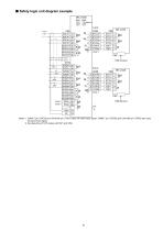
■ Safety logic unit diagram example Notes: 1 .CN8A-7 pin (TOF2A) and CN10-8A pin (TOFA) carry the same input signal. CN8B-7 pin (TOF2B) and CN10-8B pin (TOFB) also carry the same input signal. 2. Set delay time of STO output with SW1 and SW2.
Open the catalog to page 9All MITSUBISHI ELECTRIC AUTOMATION catalogs and technical brochures
-
 FX-Family MELSEC PLC
104 Pages
-
 MELFA Family
64 Pages
-
 Compact PLC Family Catalogue
122 Pages
-
 HMI-Family Visualisation Tools
90 Pages
-
 The Automation Book
156 Pages
-
 QS90SR2SP
4 Pages
-
 Q/L-Family
114 Pages
-
 ME96-NSR
32 Pages
-
 ME96-SS Series
32 Pages
-
 ECOWEBSERVER III
16 Pages
-
 PRODUCT OVERVIEW
2 Pages
-
 POWER & ENERGY PORTFOLIO
2 Pages
-
 RV-2SD-SQ BROCHURE Ver. B
3 Pages
-
 FX3S Brochure
6 Pages
-
 GT14 Handy GOT Brochure
2 Pages
-
 CNC DRIVES GENERAL CATALOG (V-M)
11 Pages
-
 FX3GE Brochure
2 Pages
-
 GT16 Handy Brochure
2 Pages
-
 FX3U-ENET-ADP Brochure
4 Pages
-
 RV-SQ-RH-SQH BROCHURE Ver. B
4 Pages
-
 ME96-SS Series Brochure
32 Pages
-
 GT14 Brochure
3 Pages
-
 F920GOT F930GOT Brochure
2 Pages
-
 FX2NC-ENET-ADP Brochure
2 Pages
-
 FX3U-1PG Brochure
2 Pages
-
 LOW VOLTAGE SWITCHGEAR
12 Pages
-
 Safety & Flexibility
16 Pages
-
 MR-MQ100 Single Axis Motion
4 Pages
-
 LD77MH Simple Motion Module
12 Pages
-
 ST Series
4 Pages
-
 GOT1000
13 Pages
-
 F900
F90016 Pages
-
 E1000
E100012 Pages
-
 QE81-WH Energy Module
8 Pages
-
 ME96-NSR Energy Meter
32 Pages
-
 CC-Link
29 Pages
-
 EnergyPAQ
2 Pages
-
 M70 Series
8 Pages
-
 C70 Series For iQ Platform
19 Pages
-
 M700V Series
11 Pages
-
 WS Series Circuit Breaker
192 Pages
-
 WS-V Series
260 Pages
-
 QS Safety PLC and CC-Link Safety
56 Pages
-
 Q Series
31 Pages
-
 MES Interface IT
7 Pages
-
 Q Series Redundant System
31 Pages
-
 iQ Sequence Controller
33 Pages
-
 Inverter family
20 Pages


Archived catalogs
-
 MELSEC iQ-R series/System Q/L series
152 Pages
-
 FX3UC
FX3UC4 Pages
-
 L Series
4 Pages
-
 COGNEX
2 Pages
-
 Programmable Logic Controllers
28 Pages
-
 MELFA Industrial Robots
50 Pages
-
 Frequency Inverters
8 Pages
-
 Global and open Field Network
12 Pages
-
 Control Units
8 Pages
-
 Melsec PLC
85 Pages

